Railroad engineers are always trying to find the easiest path from point A to point B. Many times these railroads need to cross a ravine, road or waterway and have no other option than to span the obstacle with a bridge. As model railroaders, we often use bridges to add visual interest to our scenes or span aisleways. Whatever the case, we have so many kits to choose from that it is easy for us to add them to our layouts.
I model a railroad that was constructed in the Northern California foothills. That means crossing small creeks and hills to maintain a reasonable grade. Most of the shortlines in the area used wooden trestles to cross spans, and I wanted to add a large bridge to my layout.
My freelanced railroad crosses Cherokee Creek just west of Angels Camp and thought this could be a good location to build a trestle. I also planned it that this would be the first scene that visitors would see when entering my basement. So, I wanted to make sure it was as detailed as possible.
Planning
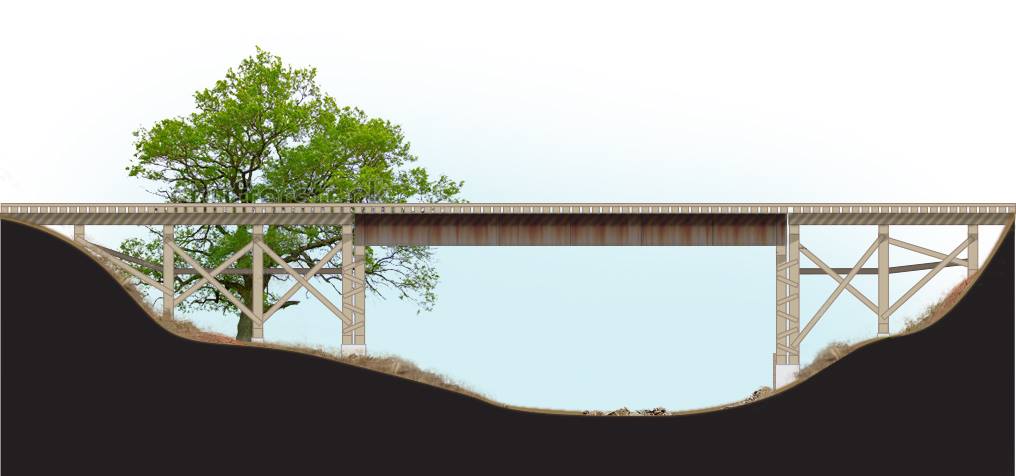
Since this was my first attempt at building a structure of this size, I was feeling a bit nervous. However, with all the research I was doing, I soon discovered that it was going to be easier than I had made it out to be. With documentation in hand, I began a drawing, first on paper. Once I was satisfied with the basic structure, I created a final rendering in Adobe Illustrator.
Next, I ordered all material I would need for the build as well as a little extra, just in case I made any mistakes.
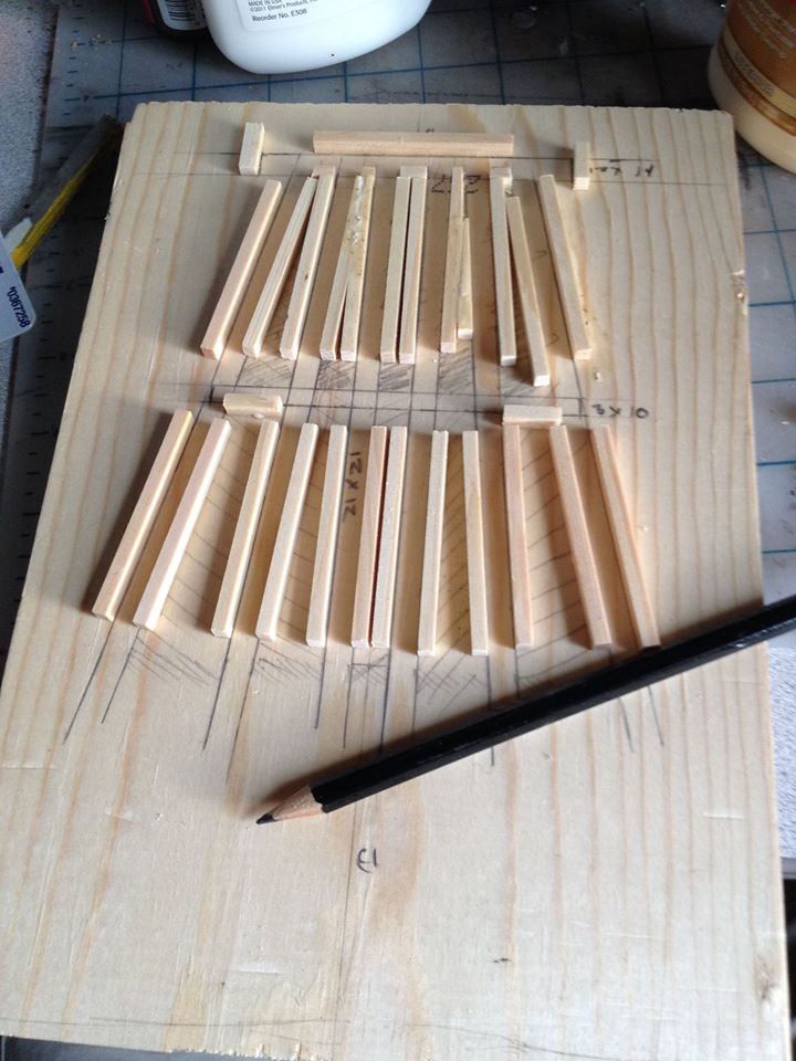
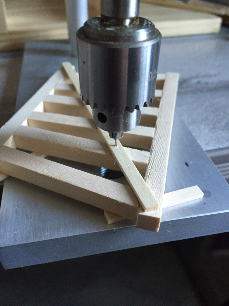
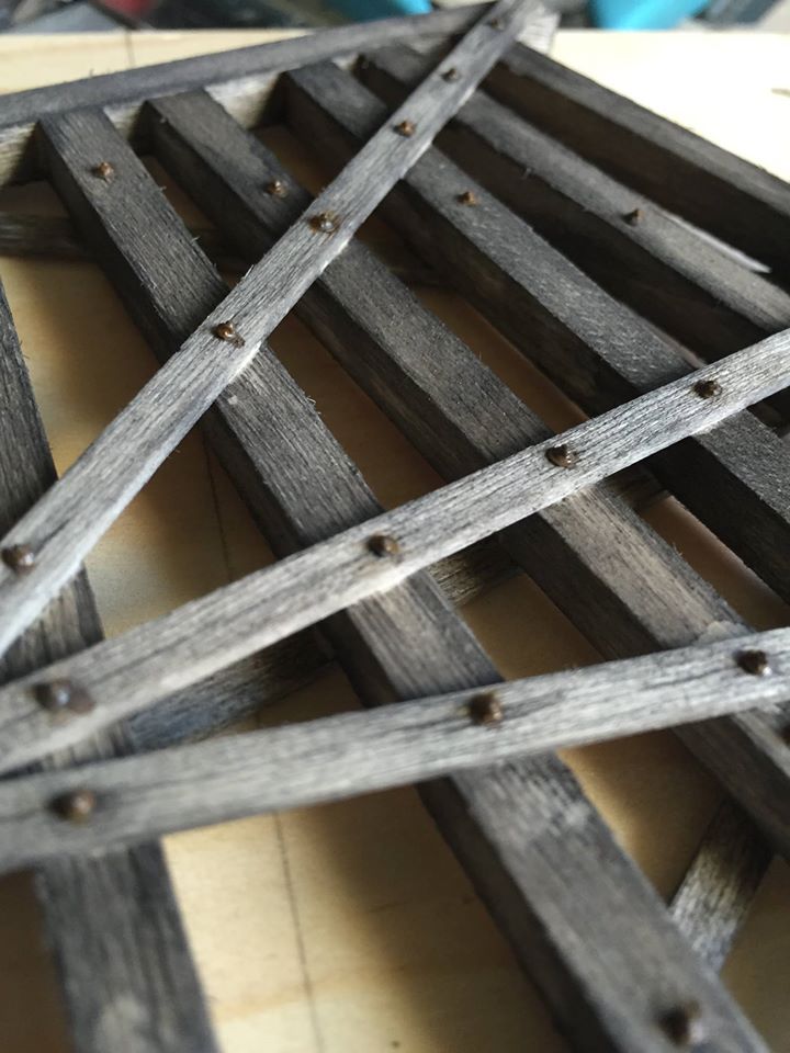
I then made a jig to build the bents using scrap lumber and stripwood I had on hand. I drew the bent on the wood, then glued the stripwood to the board. When dry I sprayed everything with dark grey paint to seal the wood.
Beginning the Build
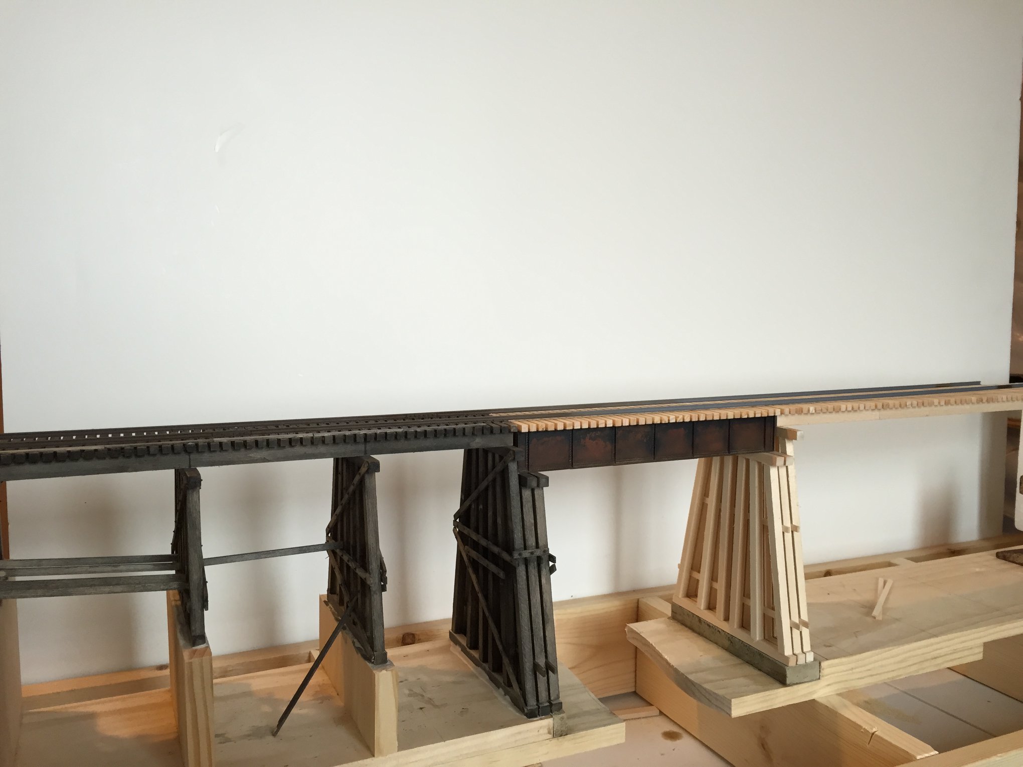
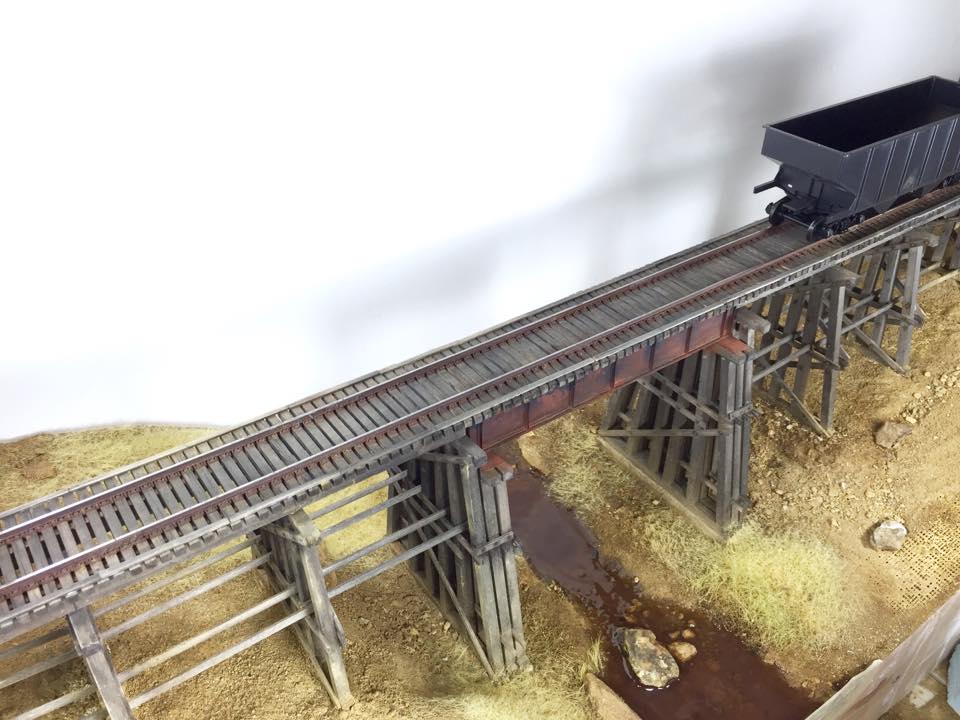
As you can see from the first drawing of the overall bridge, there will be a girder spanning the creek and so I plan on building the bridge in three parts; short approach, girder then long approach.
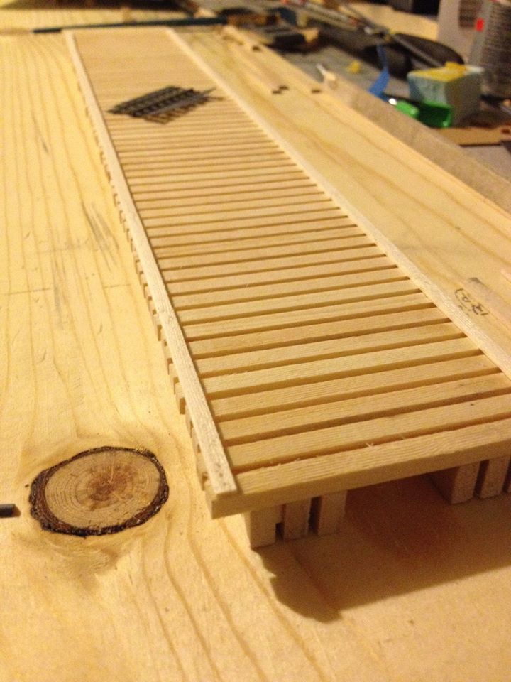
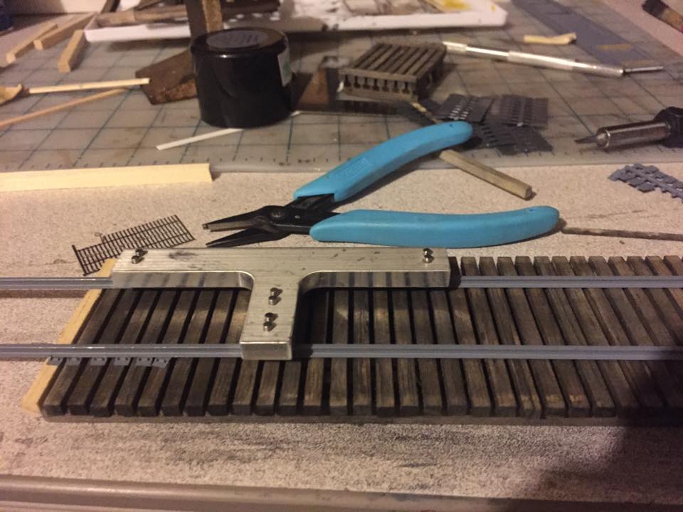
I began with the stringers and ties to determine the actual length of the short trestle. The backstory of my railroad is that it was built in 1900 and lighter equipment was used. The trestles were rebuilt in the 1930s to support heavier equipment. Typical for that period were three stringers. My layout is set in 1974, three stringer trestles would be able to support the light modern equipment I will be running so I decided to stick with three. I use stripwood to gap the stringers and then glue them together. I will then add my ties and then the timber guards.
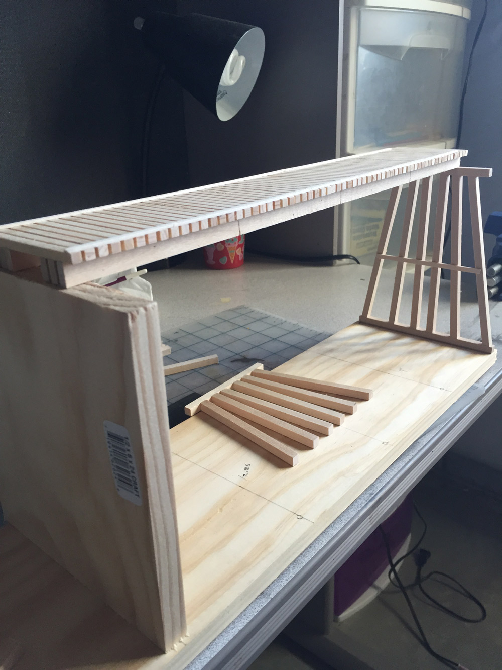
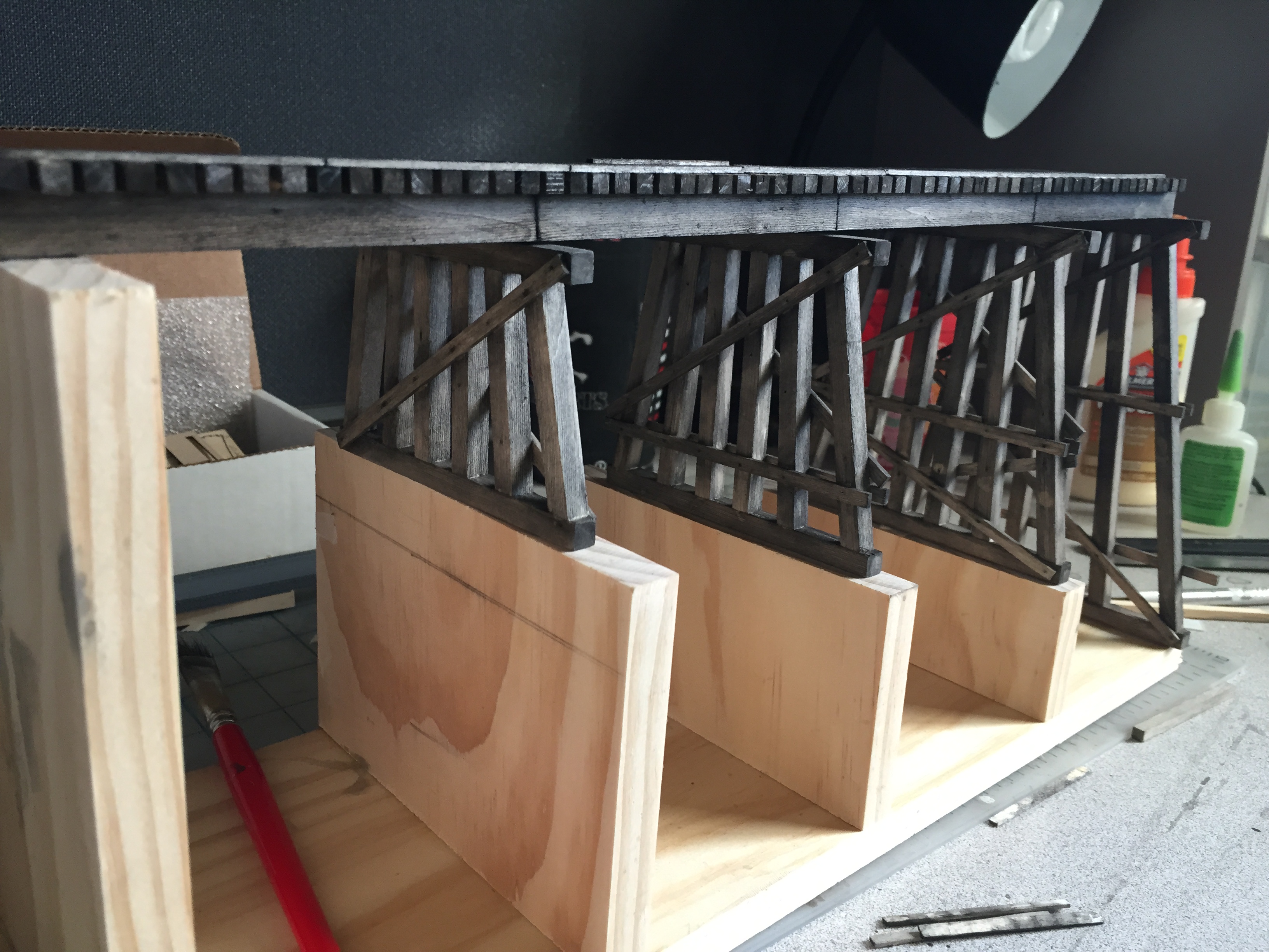
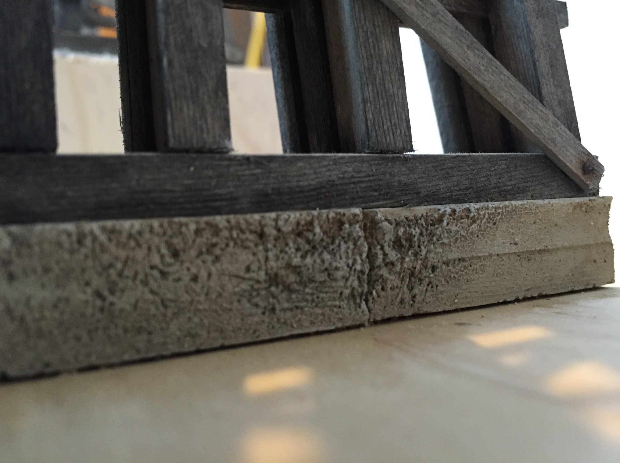
Once that was done, I measured the tallest bent to set the overall height and began building. Now that I have the first approach height and length determined, I cut woodblocks which the bents would rest on, then secured them in place. The remaining bents were built and test fit in place.
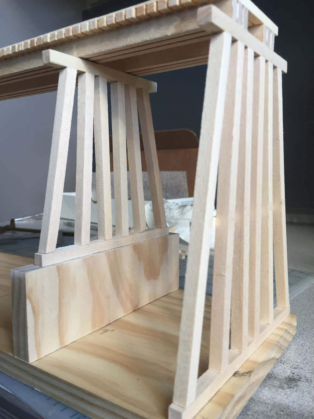
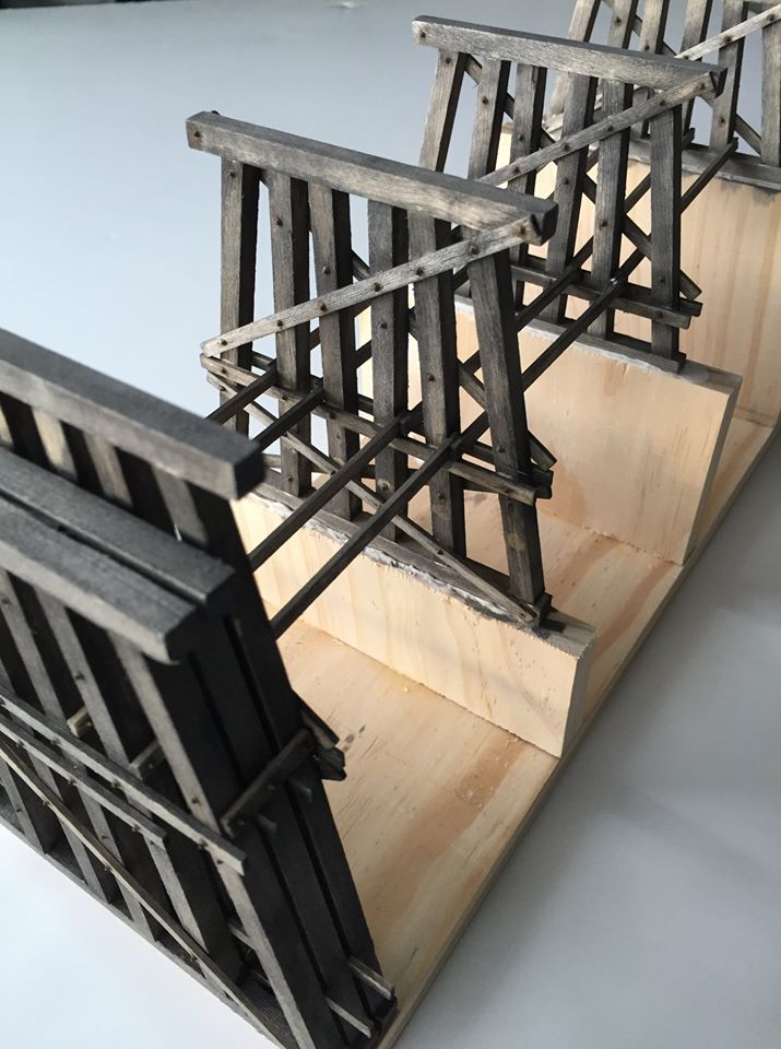
Now that my first set of bents are roughly built, I can finish them and add details.
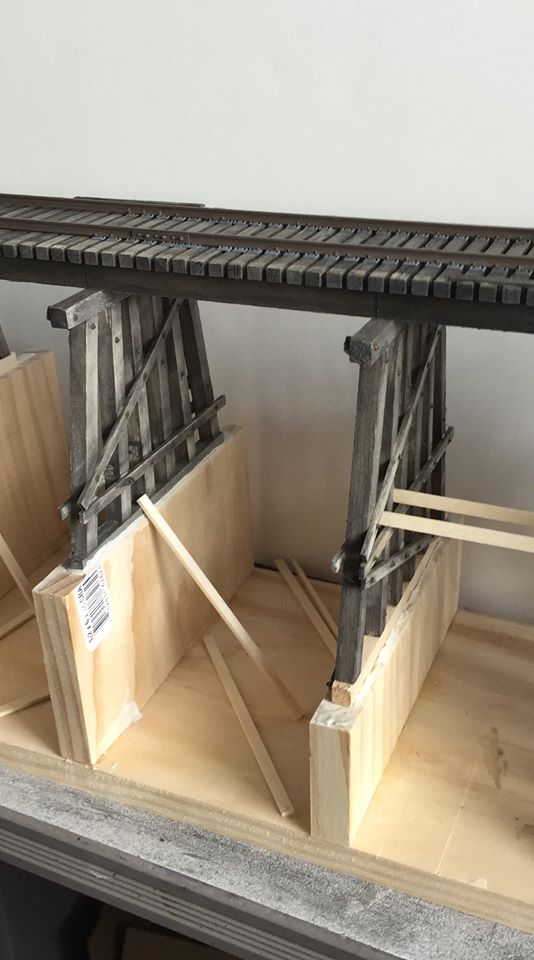
Now that everything is dry, I began gluing the bents in place. Make sure you have a square on hand to keep the bents straight vertically.
While the bents are drying, I decided to add the rails to the bridge deck. Code 125 rail, tie plates and joint bars from Right O’ Way were spiked in place with spikes from Proto87 Stores. My method for color the rails can be found here Weathering Rails.
I wrote a couple articles on the girder build, so I won’t go into detail about building; however, you can read more about the build here. After completing the girder, I began building both supporting bents. You will notice that the last bent in the above photos was not yet secured to the deck. I found it much easier to connect the three bents together on the workbench.
In the original drawing above I had one support for the girder. After some research, I decided to add an additional support and I really like the look of the second one.
The girder is then held in place so I could get the proper measurements for the supporting bents. They are build and glued together and I use pre-stained stripwood as spacers. Then I glue these to the large bent, let them dry and then set in place.
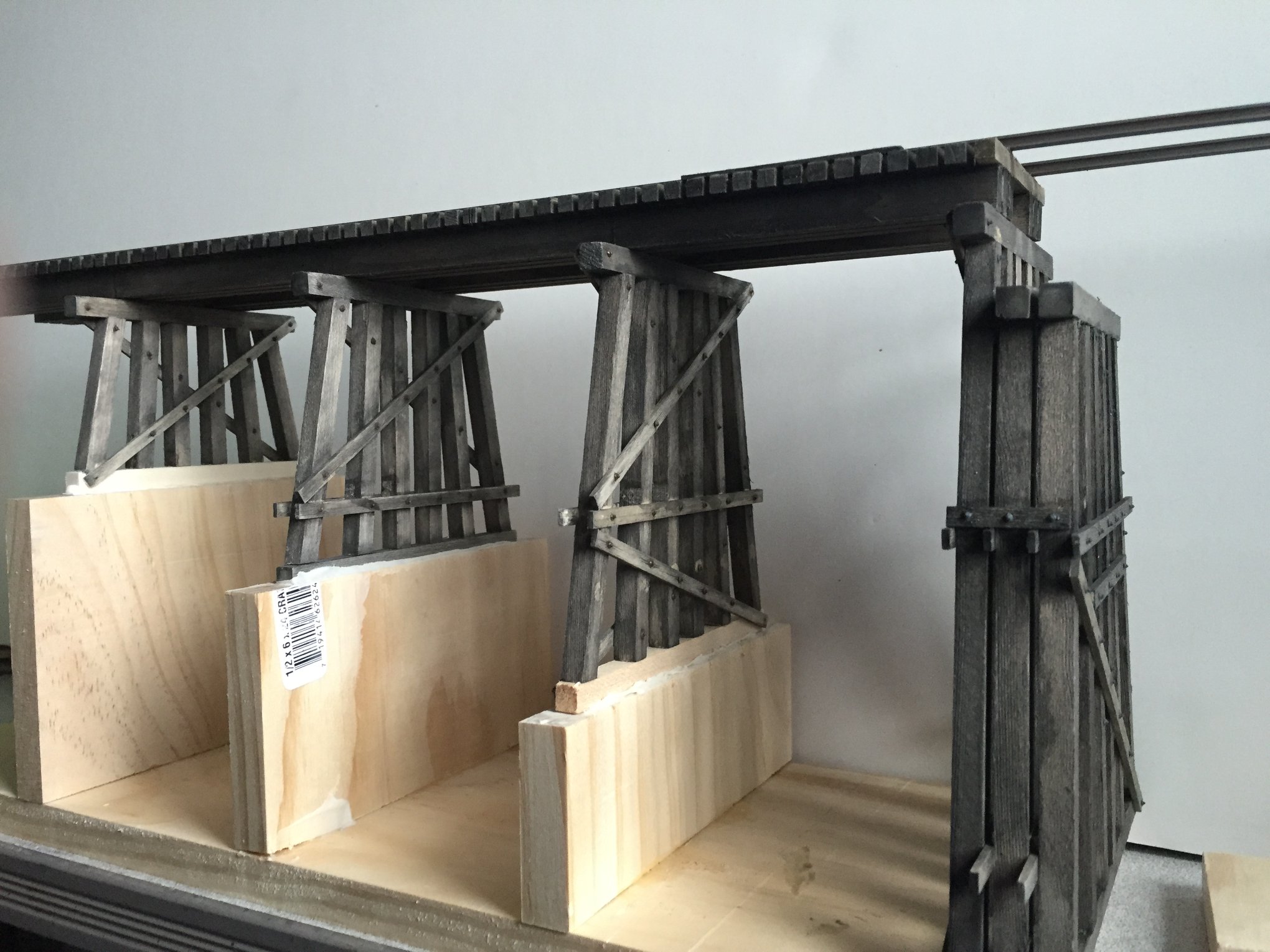
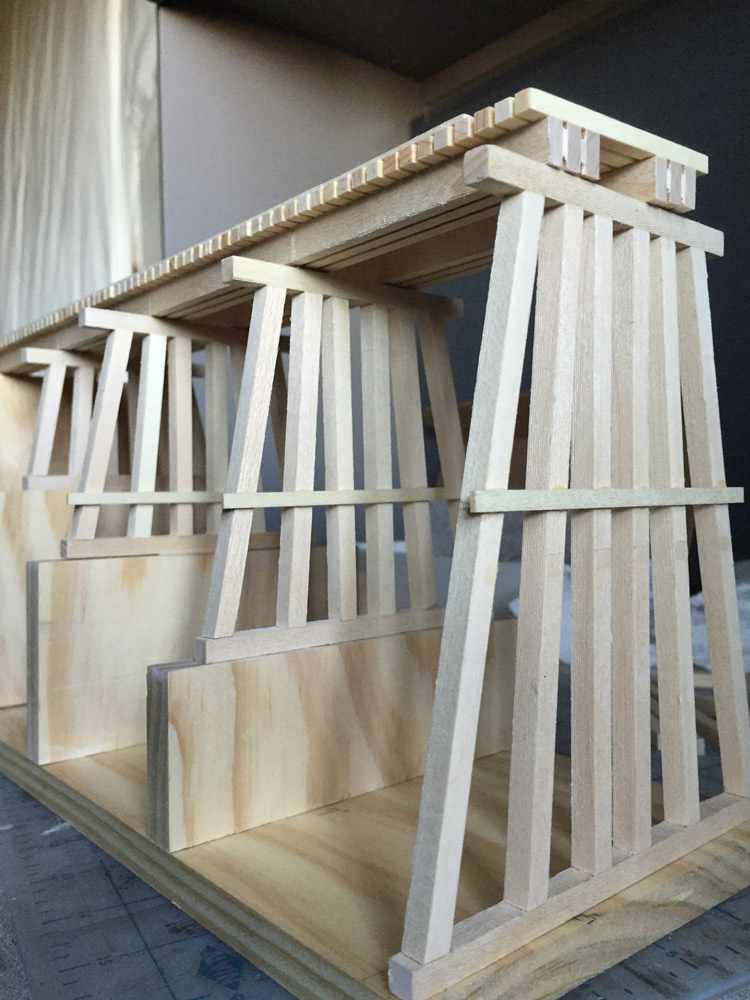
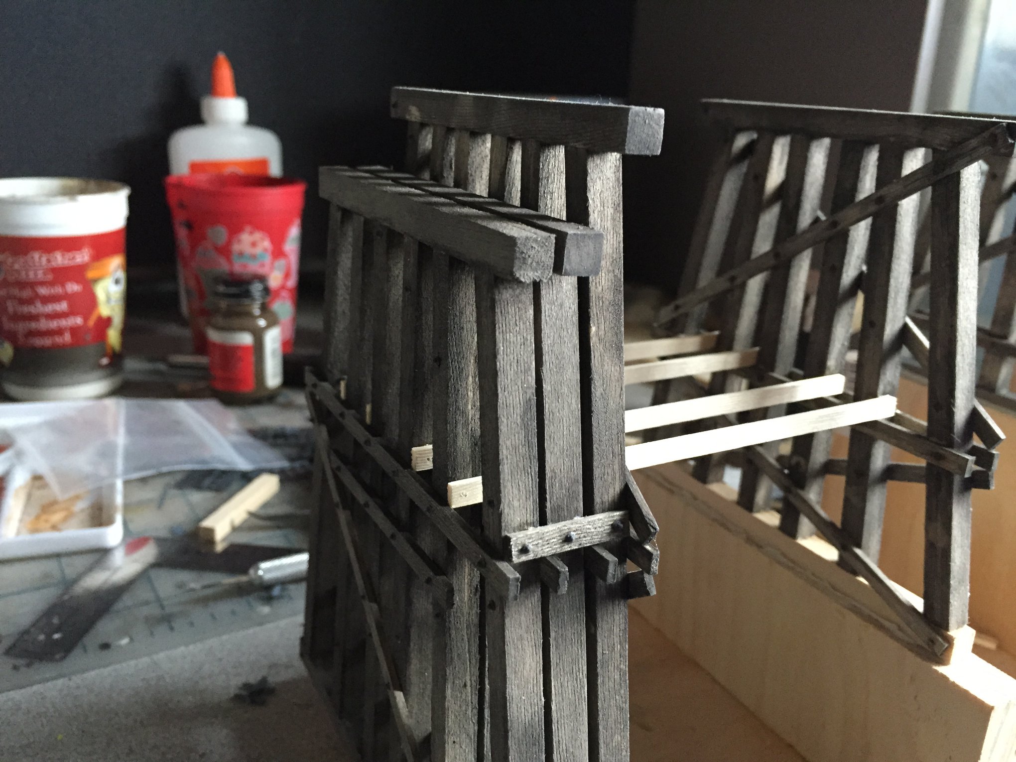
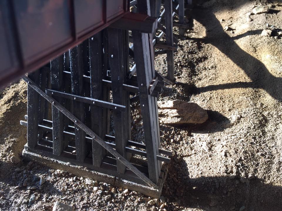
Now that the basic structure for the short approach is complete and dry, I can add the struts. These are the horizontal boards that help tie the bents together. I cut the stripwood, pre drill holes for NBW details, then glue in place. When dry, I will stain them and add the remaining NBW details and paint as I did with the bents.
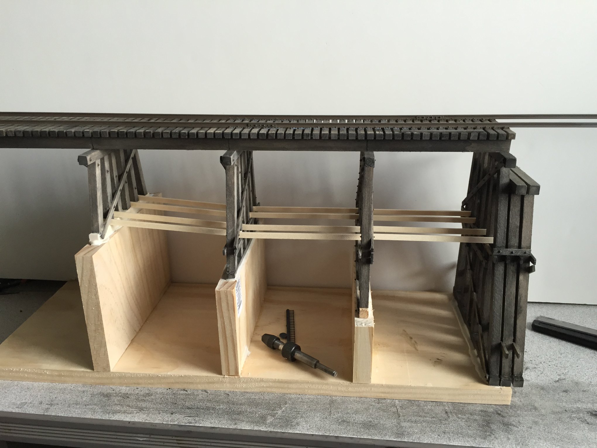
Now, it may look complicated, however, once you get basic idea of the components involved, the structure goes together pretty quick.
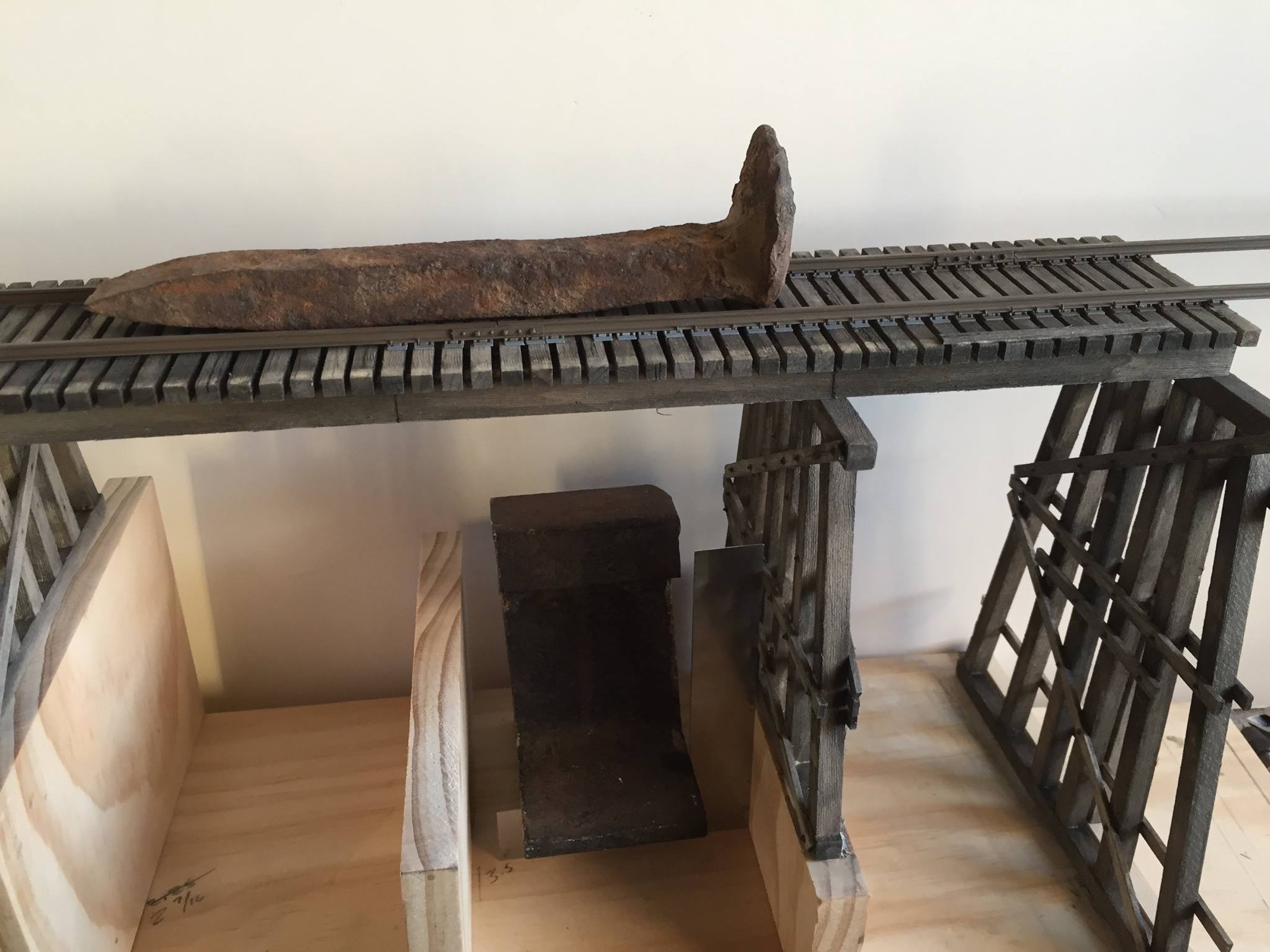
Taking a break from the trestle bents, I turn my attention to the long deck and girder. I built the long approach, adde rail then added the ties to the girder and spiked the rail to tie them together. Then this is complete, I can set it in place and begin measuring the remaining bents.
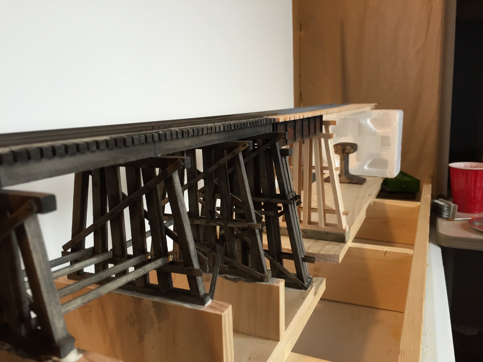
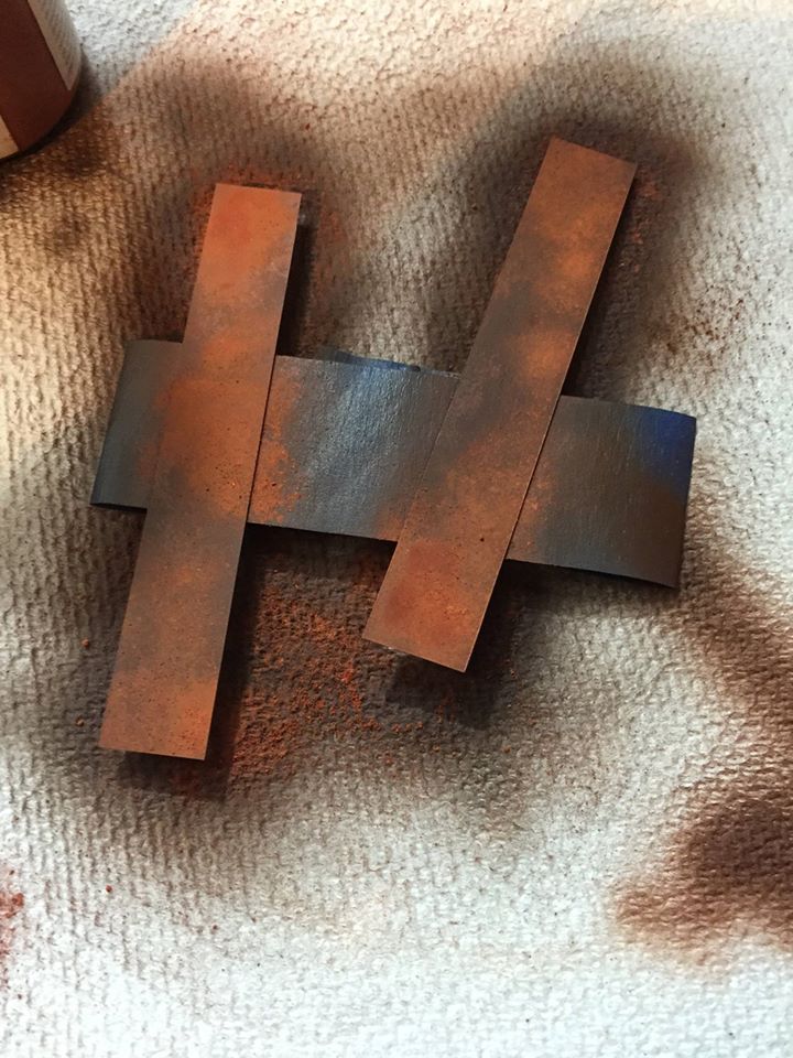
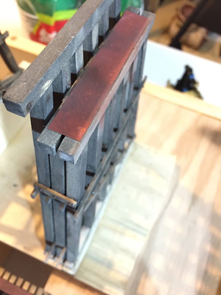
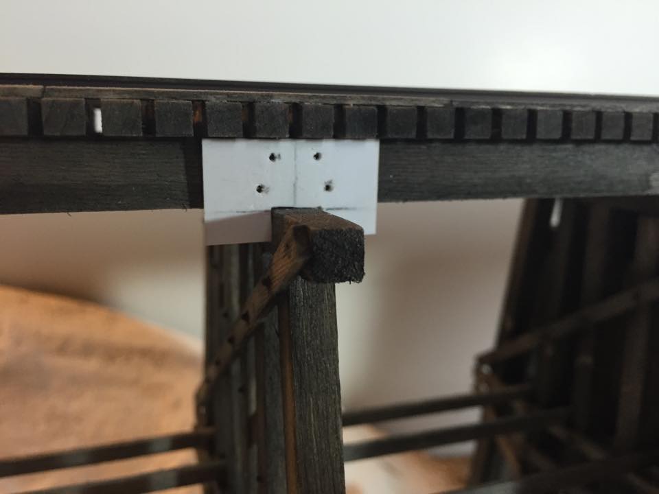
With all the bents in place, I will then add the steel footing that the girder will rest on. Most bridges use bridge shoes, however, I found a prototype that used a steel plate and I liked the look. It also gave me the opportunity to practice rusting steel. I cut .010″ styrene sheet to size and sprayed them with AK Interactive Chipping Color and Old Rust. I allowed that to dry then brushed on medium rust pigments. Sealed them with Testors dull coat and glued them to the short bents.
I add the deck and allow it to dry.
Final Details
A drilling jig was made out of styrene to locate the boles in the stringers. I then add the bolts as I did on the bents. Finally, nails and bolts details are added to the timber guards.
I hope this inspires you to build your own bridge. It is easier than it looks. With good research and plans, yoy’ll be able to build a bridge like this you will be proud of.

Very nice work! I like your approach to modeling
Thank you very much Gene!
excellent excellent work Sean
Thank you Joe!
Nicely done. Thanks for sharing your techniques.
Thank you very much!