There are a few reasons why we, as model builders, scratchbuild something; either the model is not available, we are trying to match a specific prototype, or we just enjoy the challenge. For me, this project was a little of all three. I was starting a really nice brass plate girder kit and was just about complete when it jumped off the workbench and onto the concrete floor. I tried to salvage it to no avail.
So now I had to make a decision, do I purchase another kit or do I finally try my hand at building one for myself.
The pros: I could build it in styrene and use scale thicknesses to achieve a very realistic model. I could build a bridge that fixes the span I needed without having to try and modify a kit. This will give me an opportunity to advance my scratchbuilding skills (which I desperately need). The cons: I have never tackled a project like this before and I’m not sure if I can do it.
Gathering Data
The first step to any project like this is to gather as much prototype data as possible. Even if you are freelancing, staying true to prototypical standards will greatly add to the realism and believability of your models. I did a lot of reading: Model Railroad Bridges & Trestles, Kalmbach, Lots of Google searches and finally, Edward Traxler’s blog on building a plate girder bridge.
Starting the Structure
The Girder Plates are cut down from .040 styrene sheet. These plates are the structural foundation of the model, as the prototype. I used heavier styrene here just to add a little more rigidity to the overall bridge. If you are concerned about strength, the plates could be made from brass or aluminum.
The height of your girder will be determined by the typical train weight traveling over it as well as the length of the bridge. The heavier the equipment or longer the girders, the thicker, or taller your girder will be. Since my railroad is a shortline, set in the mid-1970s, the equipment was moderate, trains short and the locomotives were two-axel, first or second generation GP’s (maybe some light steam if I ever backdate the layout).
The first structural pieces I placed were the Flange Angles, which are .080 styrene angle shapes. I glue them flush to the top and bottom of the outside with Testers plastic cement and allow to dry. Next, I glue the inside angles in place.
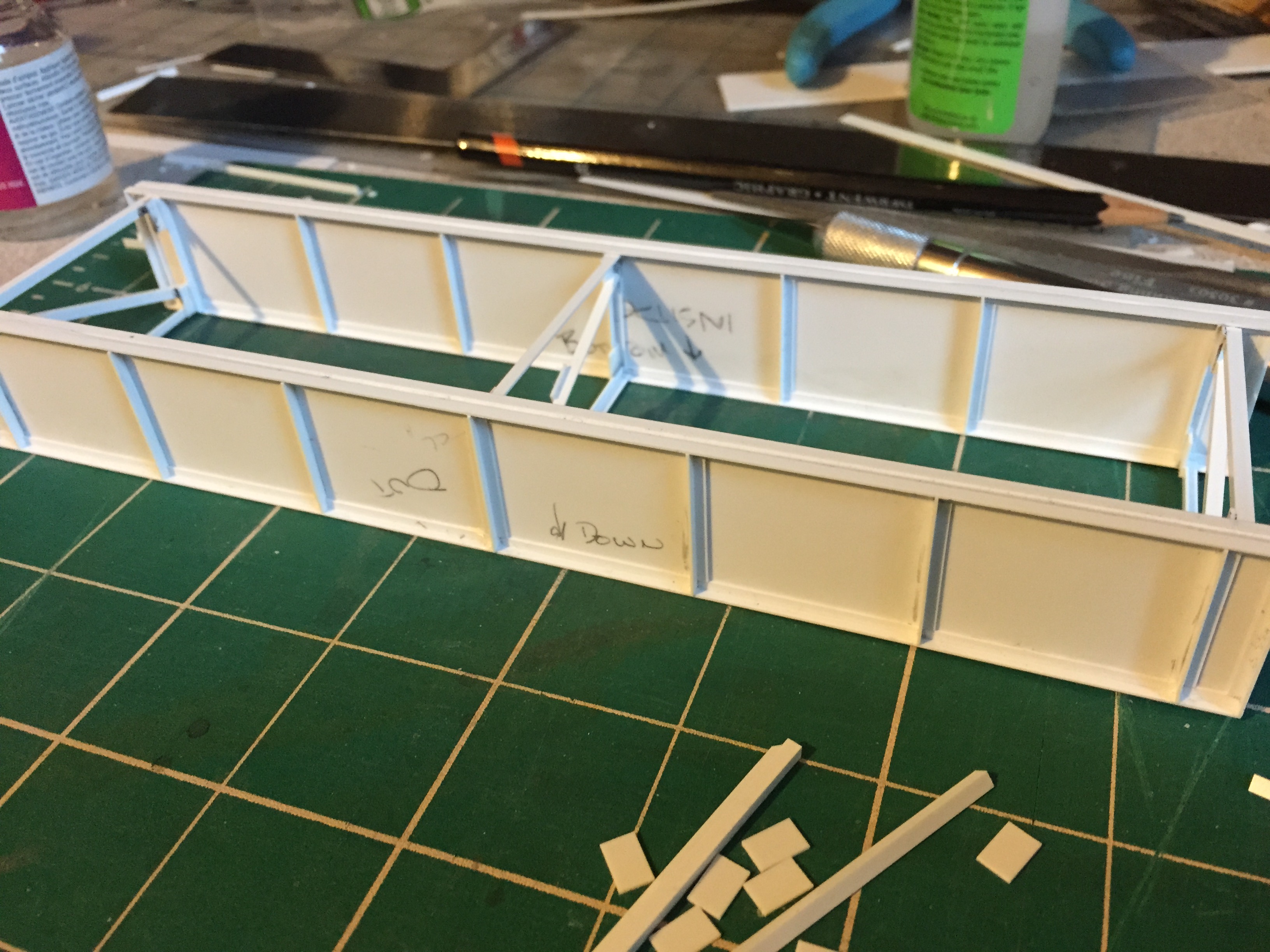
Once these angles are completely dry, I can move on to the End and Intermediate Stiffeners. You will notice at this point your plates are starting to show less flex with the angels in place.
The stiffeners job is to do exactly what their name implies; stiffens the girder structure. There are a few different types of stiffeners, however, the most common I have found for my era are in the drawings below. Using the same angle material, mark your lines on the plates and glue them in place. My center stiffener was created by cutting a piece of angle material in half and glutting it to the opposite side of the angle.
Once all are in place, allow them to dry and then we can begin work on the interior bracing.
You will notice that there is no rivet detail at this point. My plan is to use decal rivets from Micro Mark. Archer also makes printed rivets that are slide decals. More about that later.
Bracing
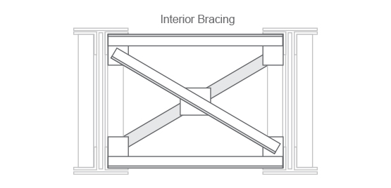
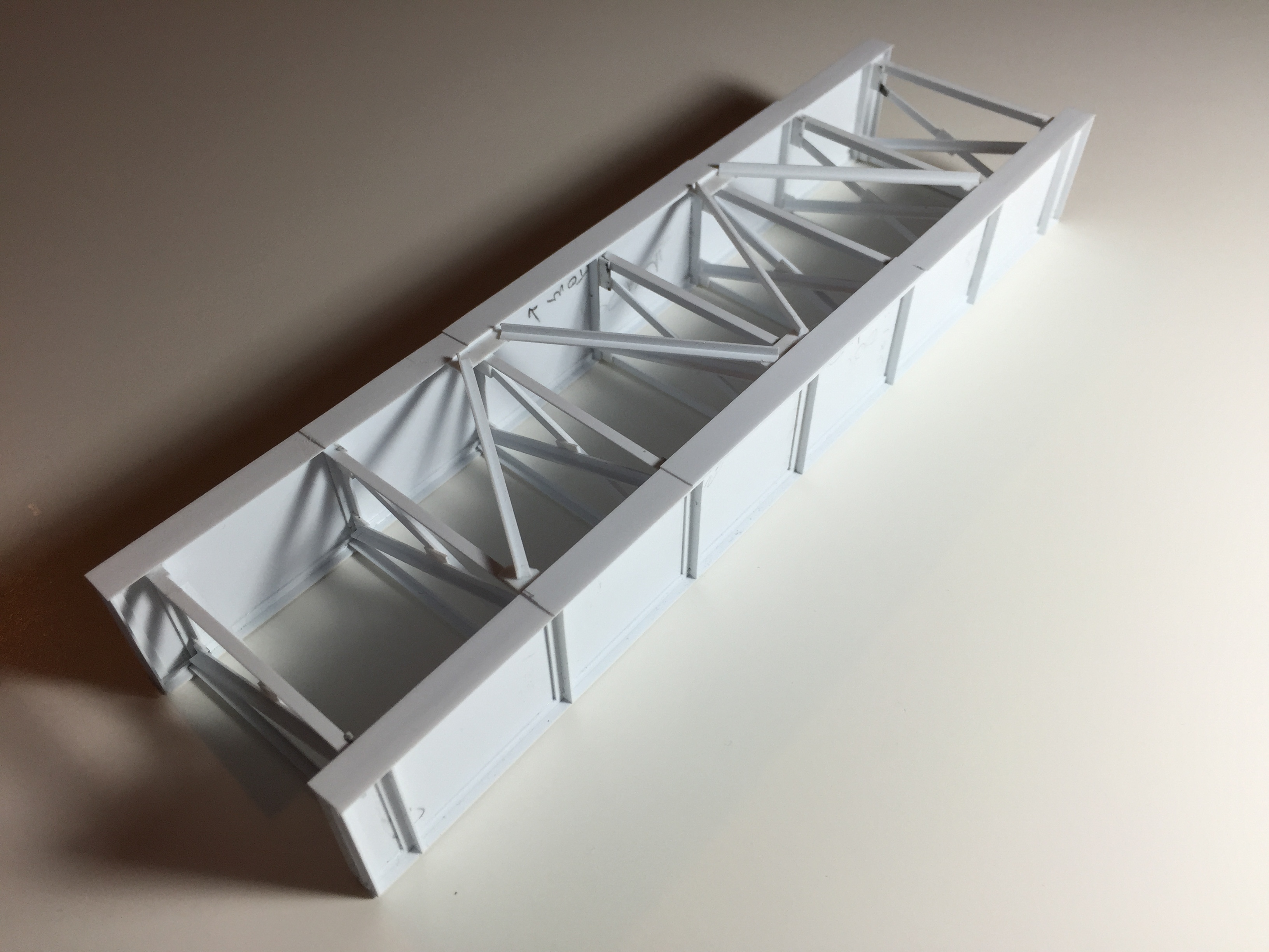
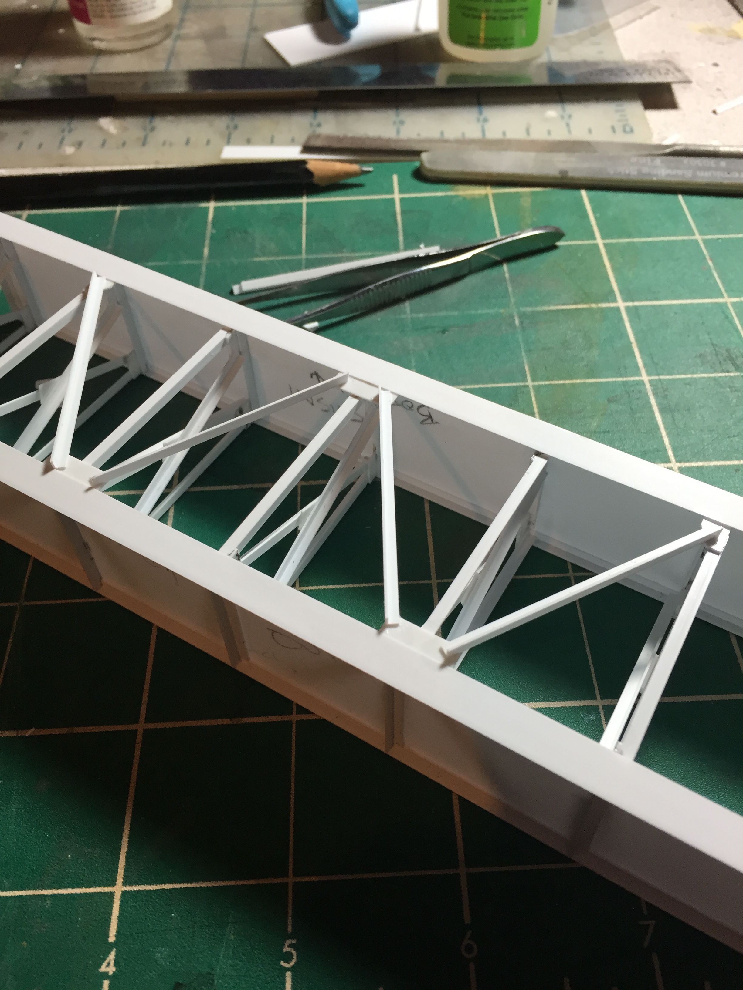
The interior bracing may look complex, however, once you have a good idea of all your materials involved, the build moves fairly quickly.
The each one of the deck girder’s cross frame bracing consists of two horizontal bars attached to steel plates which in turn, are attached to the beams at each stiffener. Finally, two additional bars are attached like an “X” to the top and bottom with a spacing plat at the center where they cross over. It looks complicated, but it’s not.
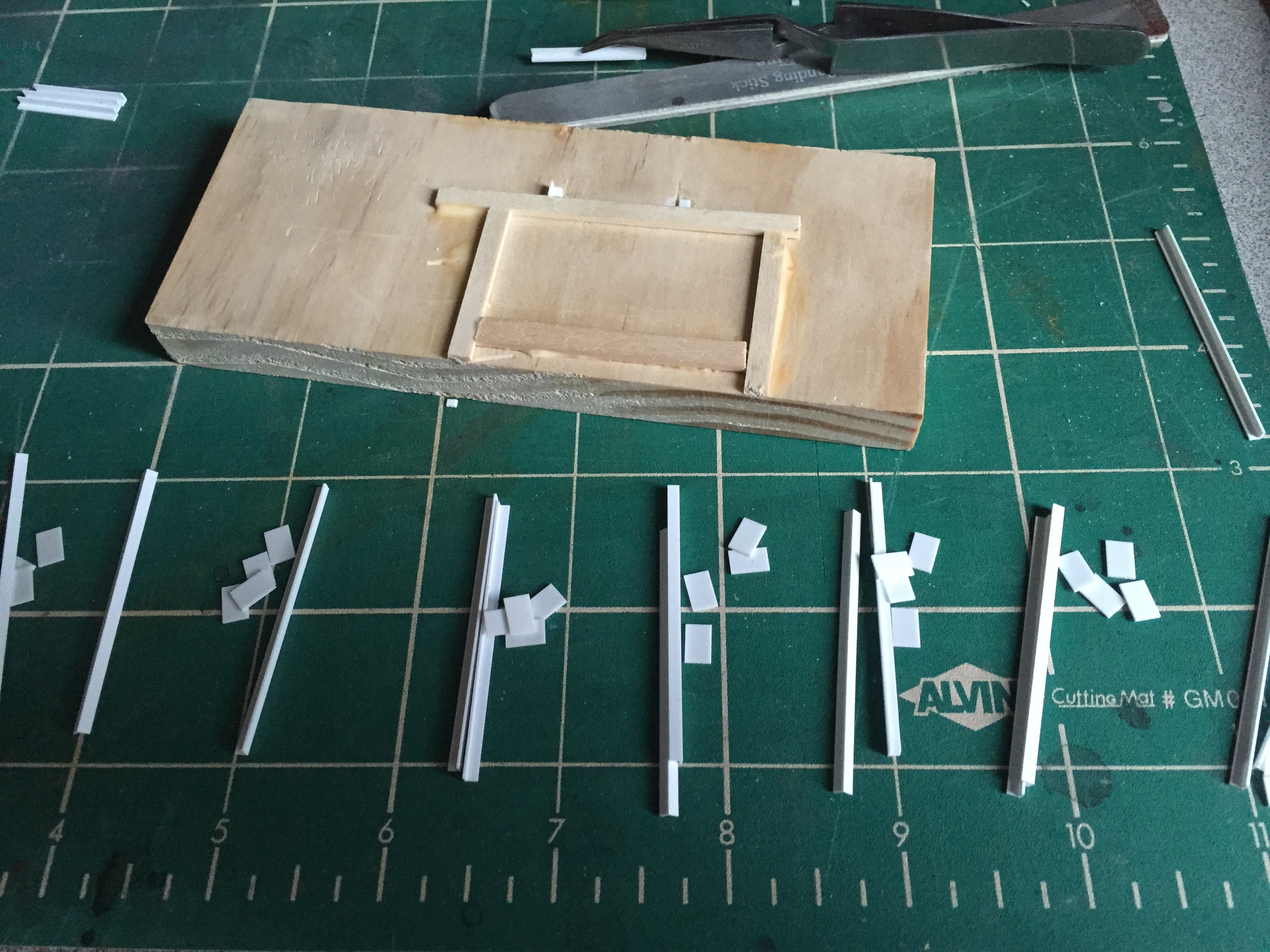
To build this, gathered my dimensions, cut my material to length and created a simple jig to assemble everything. The jig is nothing more than a scrap piece of 1” x 4” scrap lumber as the base with strip wood from my scrap box used for the frame.
I glue each one together and allow them to dry before I attach them to the girder beams. You will notice that I did not glue the second cross member to the bracing yet. This was strictly a personal choice to add them once they were led to the beams.
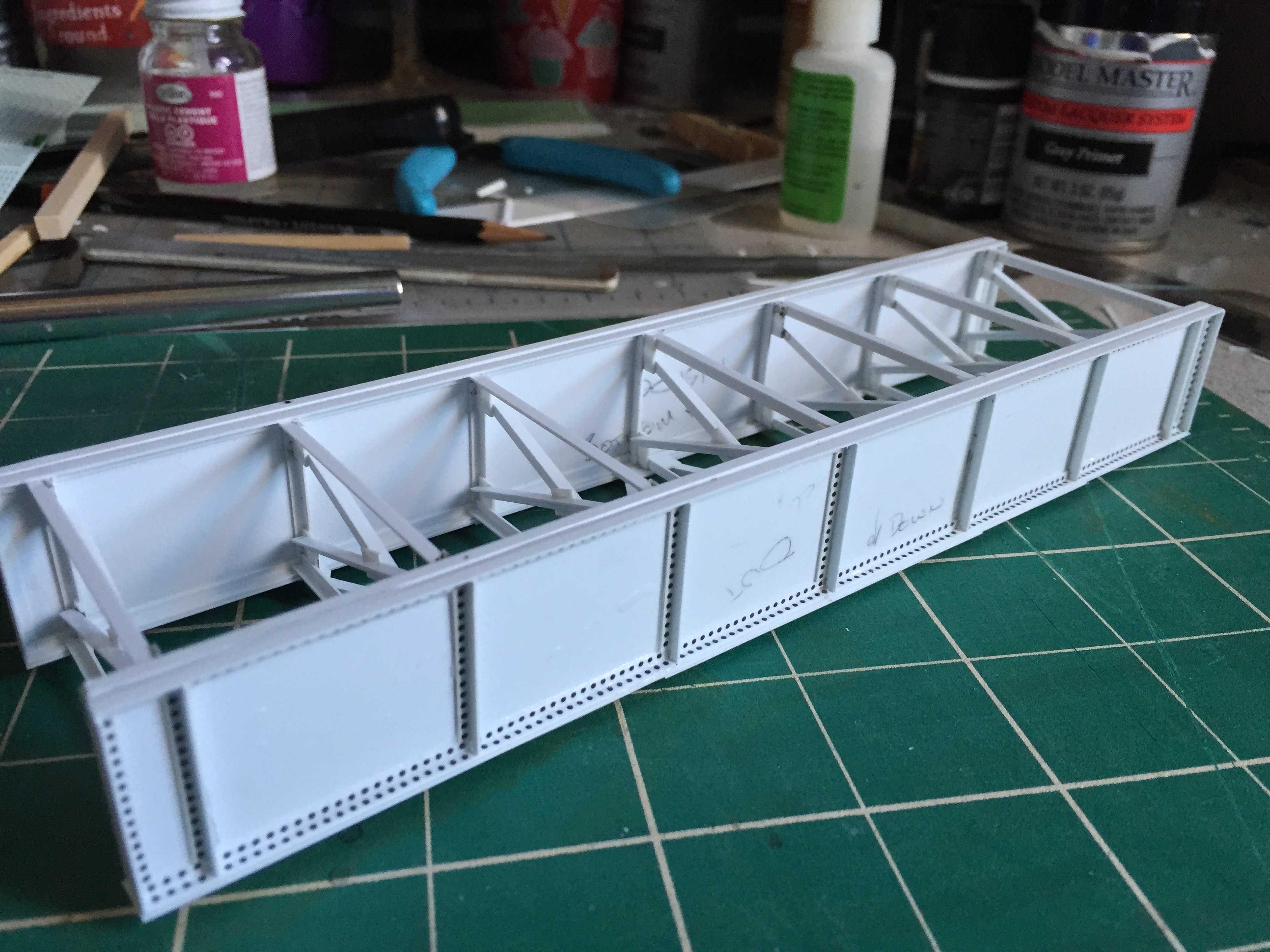
Flange Plates
The flange plates are steel plates that run the length of the top and bottom of the beam to add even greater strength. Additional plates will be added to the top and bottom near the center outward to provide even more.
I created mine from .010 x .250 strip styrene. The strips were cemented to the top and bottom, allow to dry and then finally cut to length. Two additional plates were added to the bottom however because you will not see the detail on top, I did not add the additional pieces to the top. After these are dry, I can move on to the bottom diagonal braces.
Diagonal Braces
To finish out the structural components, I will add the diagonal braces to the bottom of the bridge. The diagonal braces are there to prevent any sway that might occur. Heavier bridges will use a similar pattern as the interior braces, however, my bridge is light and shorter so I will be using less material. Using the angle strips, cut each one to length. Again, these are attached to the bottom of the flange angles with steel plates. Using .010 x .250 strip styrene I cut these plates to the desired length and glue them in place. Then I attache my angle braces.
Rivet Details
As mentioned earlier, I am using printed decal rivets from Micro Mark. Archer also sells a wide variety of rivet arrangements as well. These are raised resin dots printed on slide decal paper. Since this was my first experience with them, applying them was a bit tricky at first. Soon, I got the hang of them and the process went fairly quickly although tedious.
To apply, I sprayed the entire model with gloss varnish to create a smooth service for the decal to stick to. Working with the stiffeners first, I cut strips of rivets to length, soaked them in water and applied.
I added rivets to the bridge as the prototype, however, I did not add them to the interior. Since the detail would never be seen, I decided to leave them off.
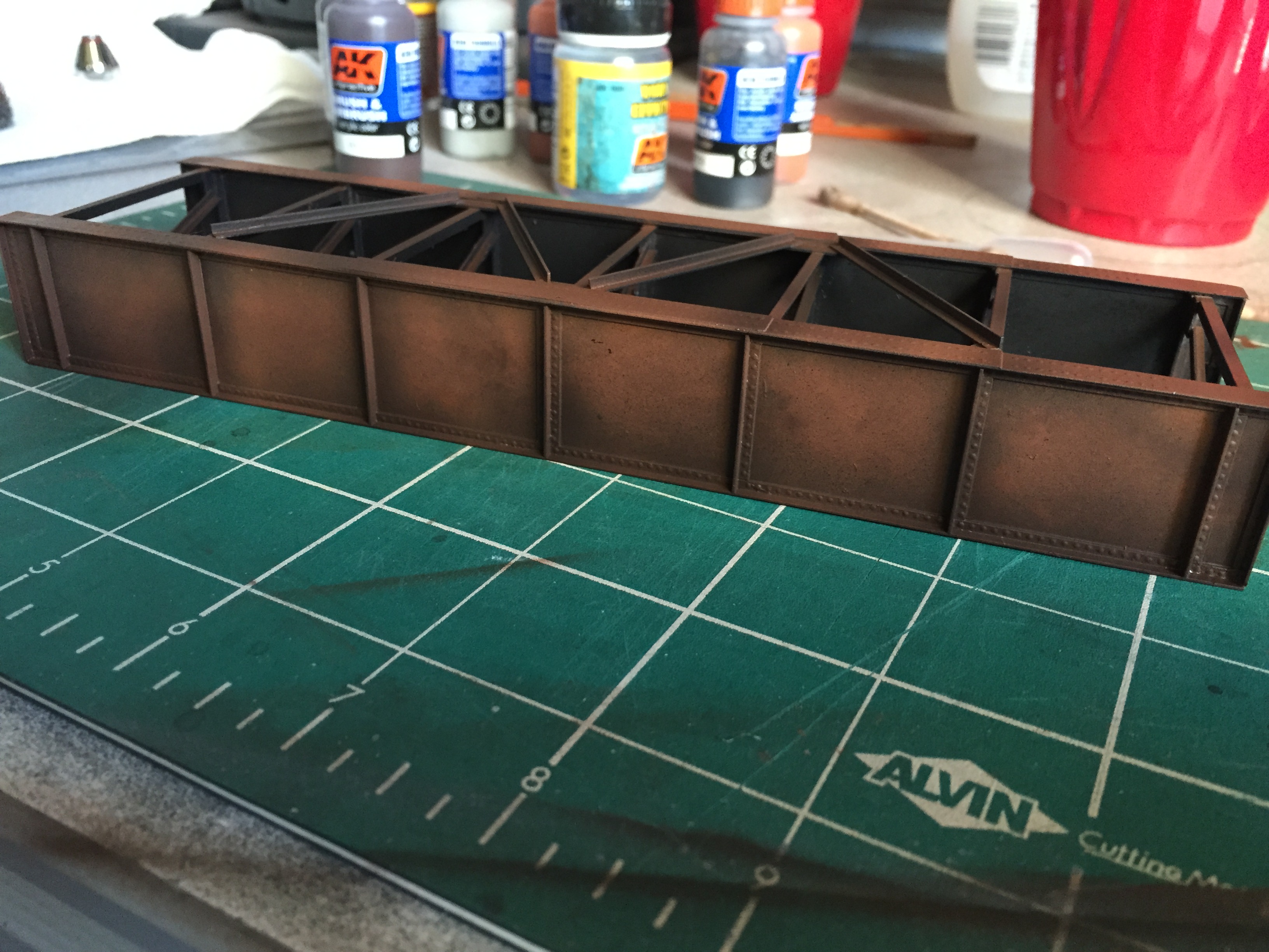
The entire bridge was sprayed with a foundation of Dark Rust from AK-Interactive. Then I switch colors (I don’t clean my airbrush between colors) and the corners were sprayed with AK-Interactive Shadow Rust to add shadows in the appropriate areas.
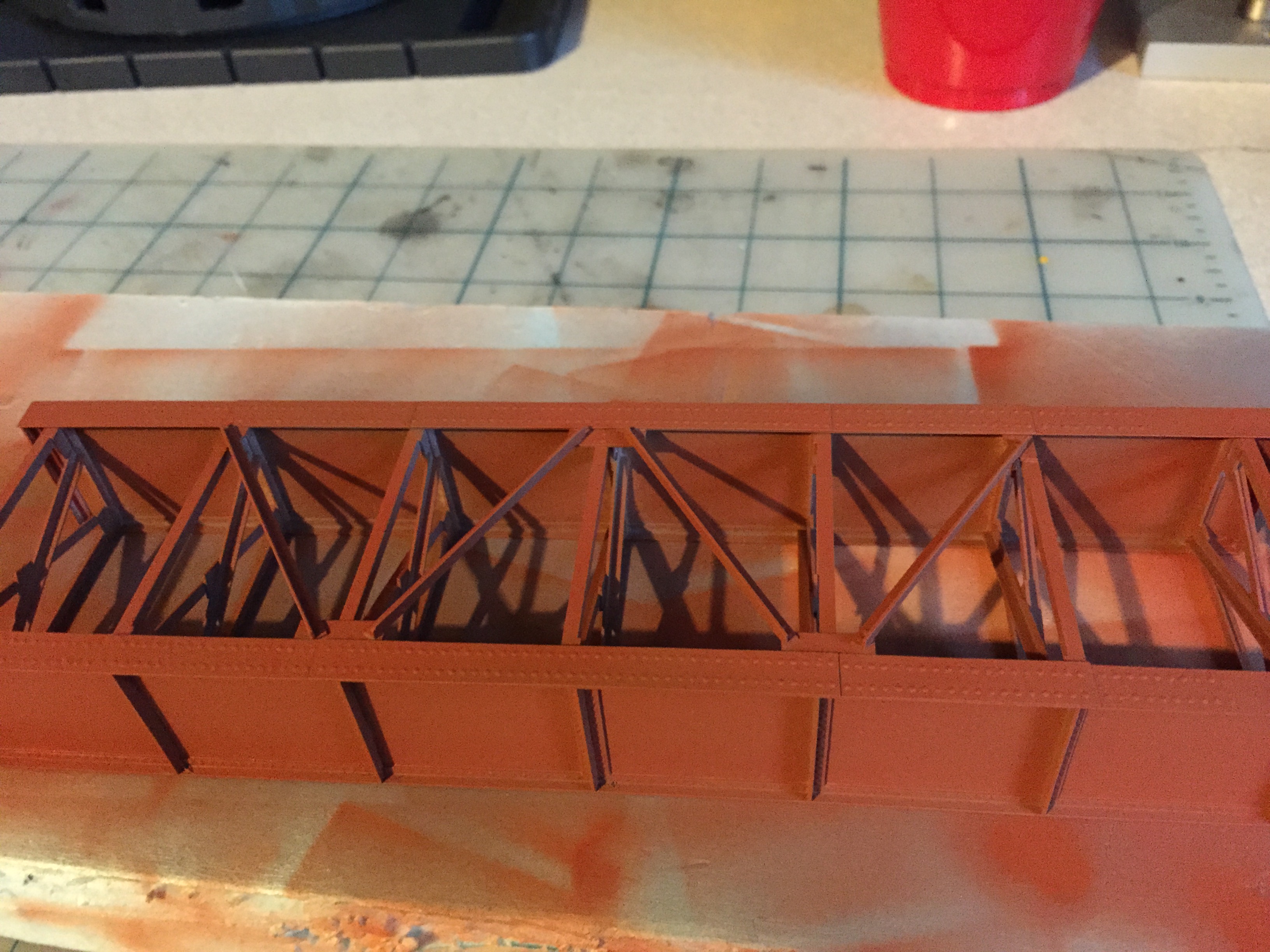
Then, still not cleaning my airbrush, I spray the interior flat black to darken and hide the areas that are not going to be seen very well. Back to my Dark Rust color to add highlights to the bracing that will be seen followed by the shadow Shadow Rust.
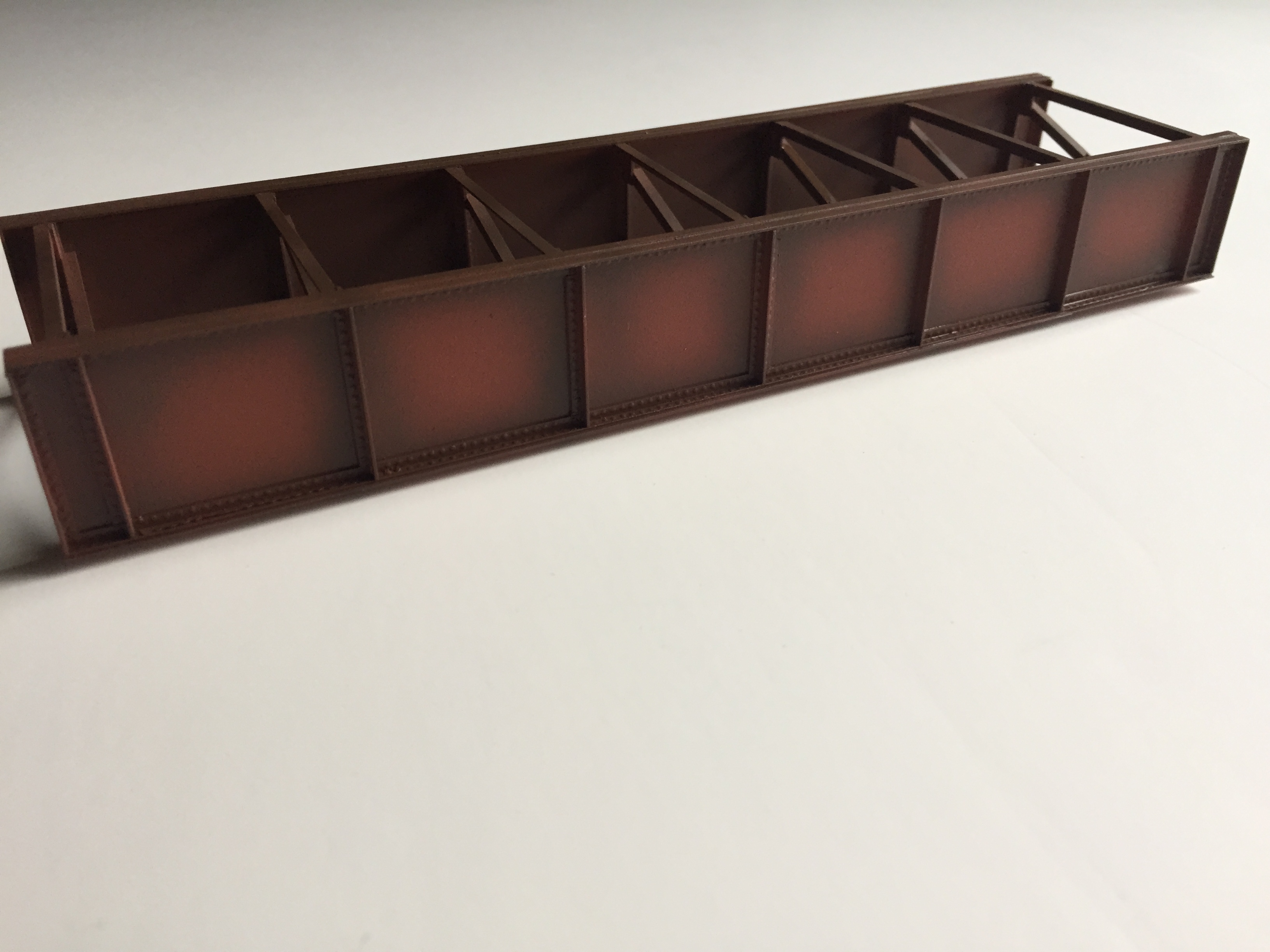
Next, to add dimension to the rust and peeling paint, I brush on the Heavy Chipping Effect fluid by AK-Interactive. Allow it to dry and lightly spray Chipping Color to the areas where your paint is going to be pealing. Using water, wet a soft paintbrush and then lightly remove color in the corners or any area you want your rust color to show through.
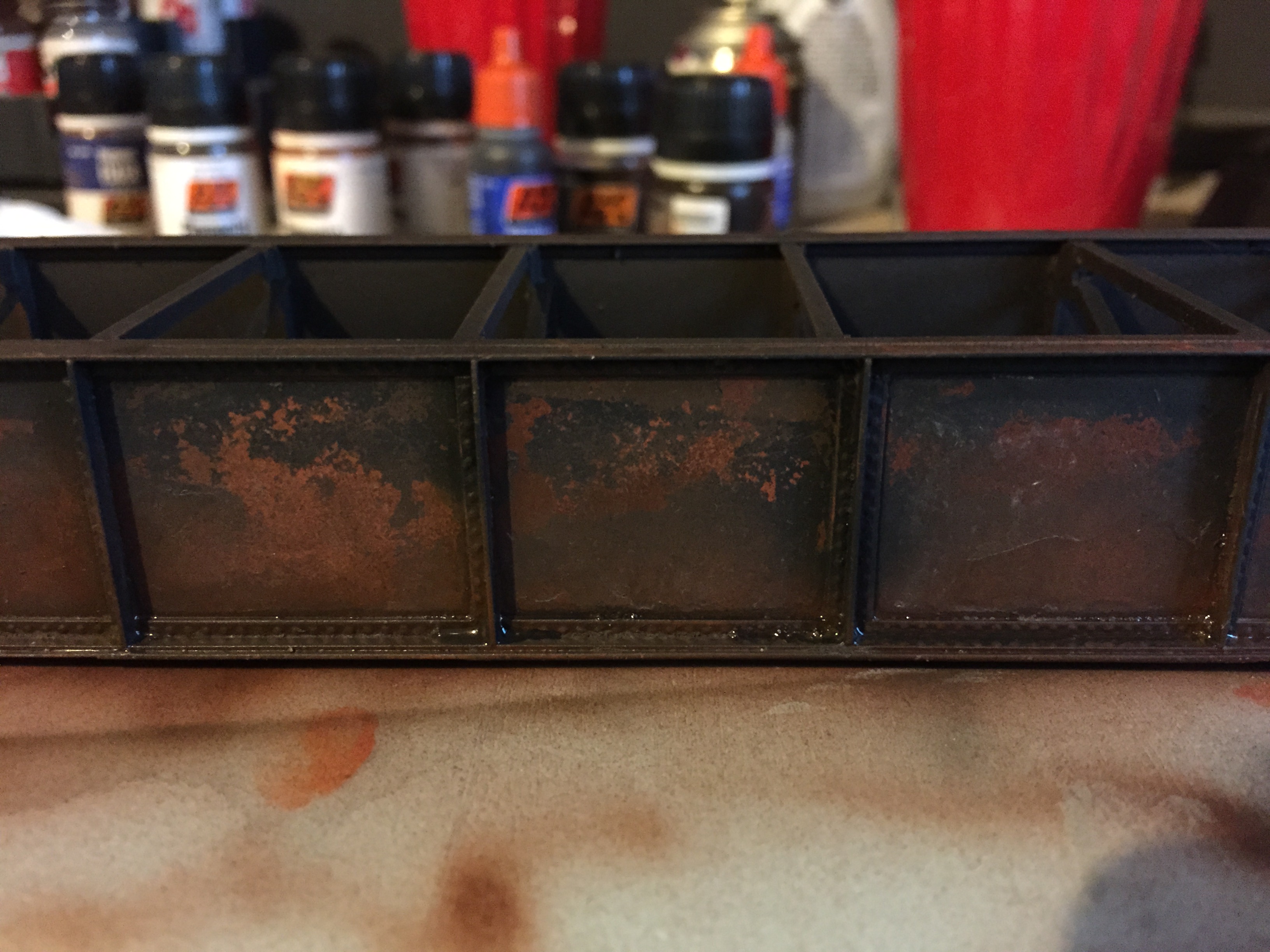
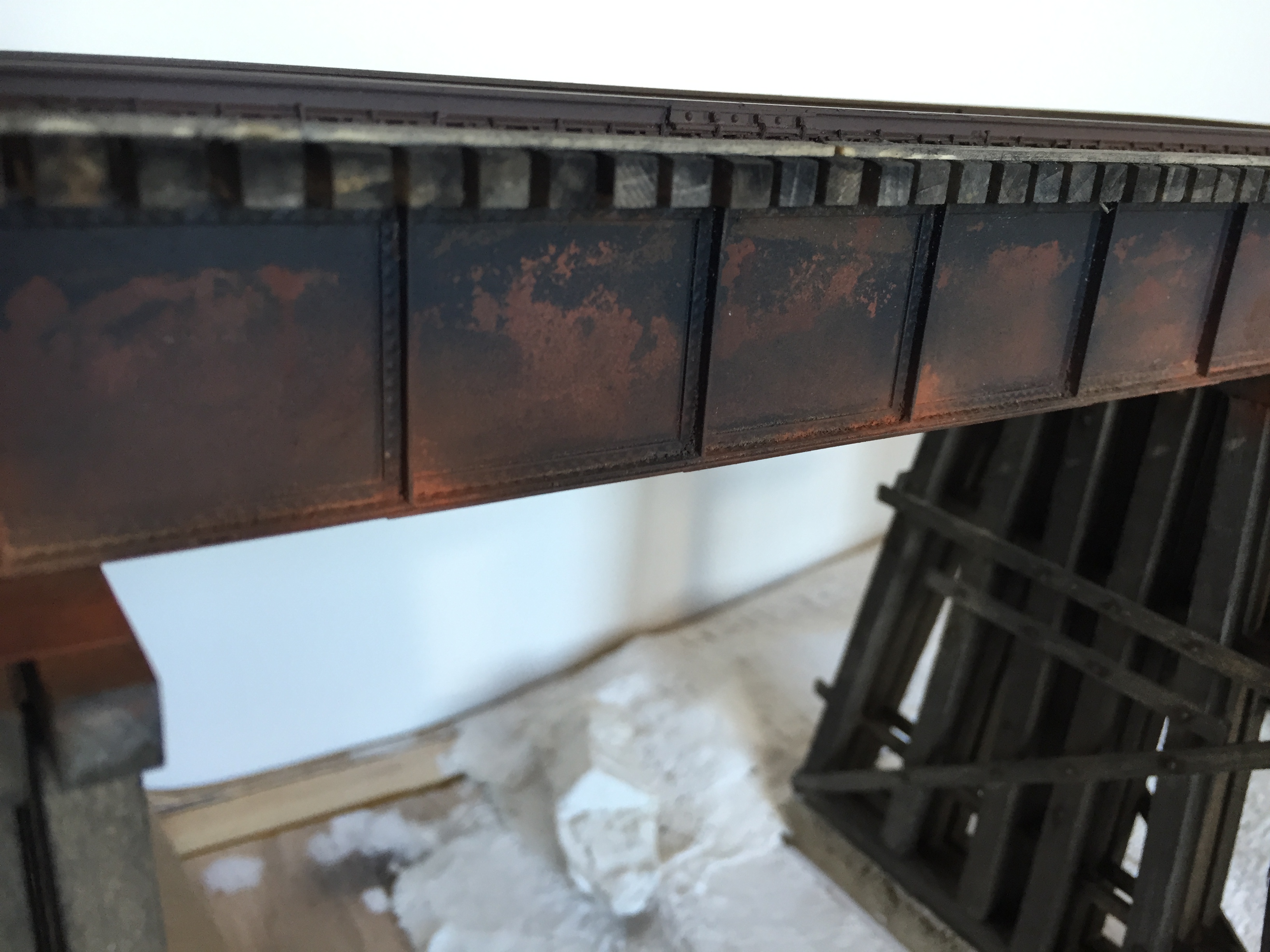
Now for the top coat. My bridge was, at one time, painted black. The weather and time have caused it to be mostly rust. I will brush on a heavy amount of the Heavy Chipping Effect and then carefully spray areas of the model. You will notice I faded the black into the rust color so you will see chipping and fading on the bridge. Again, using a soft brush with water and then lightly remove color.
To finish off the weathering, I dust on Medium Rust pigment from AK-Interactive followed by real dirt. I then spray on a coat of dull varnish and then call it complete.
I encourage you to try scratchbuilding. Once you get the hang of working in your preferred building material you will find your model building possibilities greatly increase. As will your enjoyment with the hobby. It continues to for me.

Impressive work .. as usual
Thank you very much Ed!
This is a useful article with great detail about how to start scratch building a plate girder bridge. Many thanks for your help. Cheers, Paul
Thank you Paul!
Excellent article, Paul! You have inspired me to scratch build a model of a deck girder bridge for a diorama I’m planning on the Kettle Valley Railway in British Columbia. I’m starting my order for styrene. An important question: is your model Ho or O scale? Great work, love your painting skills.
Thank you! I’m modeling in O scale.
Sorry, I meant Shawn. What size angles did you use for bracing?
If memory serves me correctly, I used 1.5mm angle styrene.