Building the Angels Creek Bridge and Creek Bed
As the mainline was moving West to the shops, I paused for a moment in order to work on the Angels Creek section of the layout. As I have been working out ideas, mainly in my head, this scene has been continually daunting. I’m not sure why, however, I do know this scene is going to push my modeling skills. I believe my last count was 4 trees in this area and I have never modeled a tree before. I have started practicing but more about that some other time.
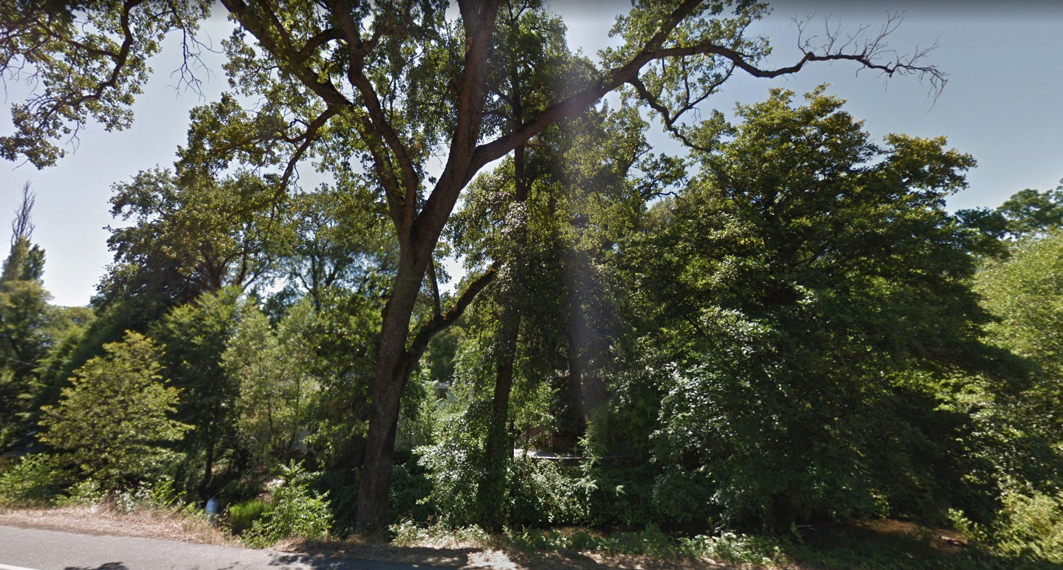
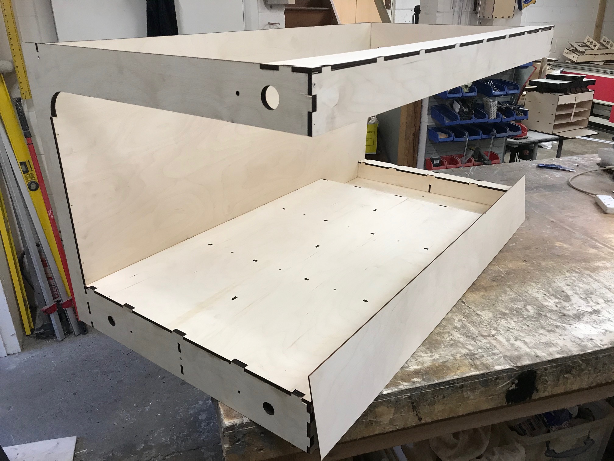
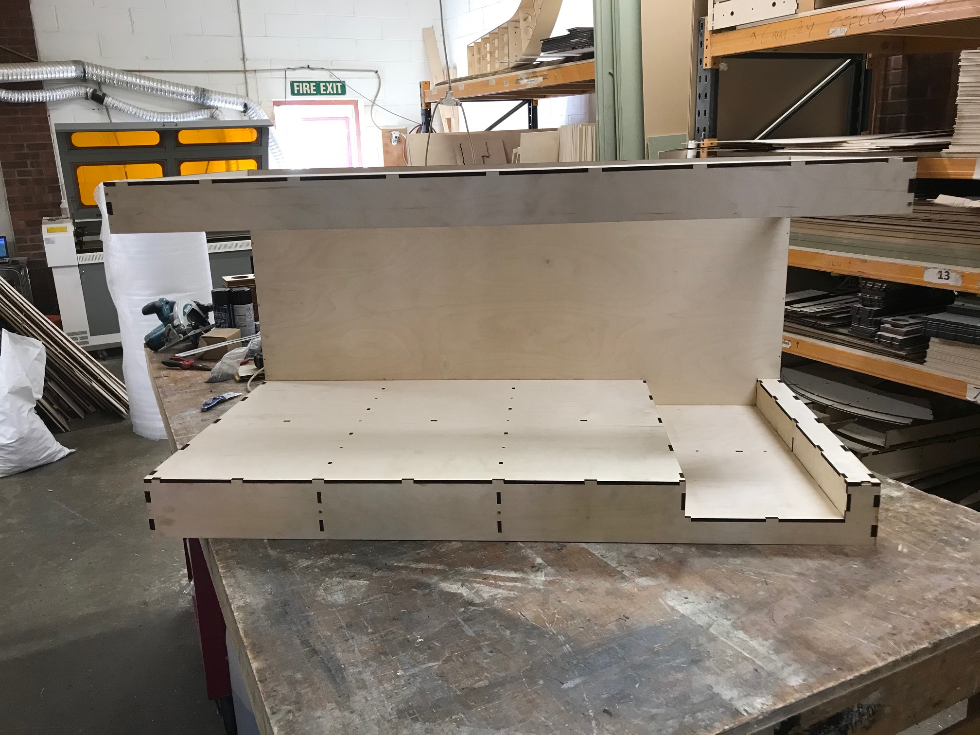
Growing up in Calaveras county and driving on Highway 49, you will eventually cross this creek. I did many times and love the area around it so naturally I wanted to find a place for it on my layout. For those following along, Tim Horn was kind enough to add a 2-inch drop in the module baseboard to accommodate the Angels Creek scene. The width of the recess is 10-inches which will allow me to build a short trestle approximately 39 scale feet in length.
Designing the Scene
I did take some artist license and change the location of Murphys Grade Road. In real life, the road is about a mile north of the creek. Moving the road a bit closer adds a bit more visual interest and some contrast to the overall scene. I am planning to add a couple of structures to this area to add even more interest, however, I have not yet finished that plan.
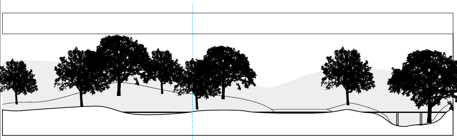
A rough sketch of the scene was made then drawn on my computer to give me an idea of what the overall look was going to be. Happy with it, I went ahead and started workin on the land forms. In a previous post, I did mention I started adding scenery to the area to test some material and my skills.
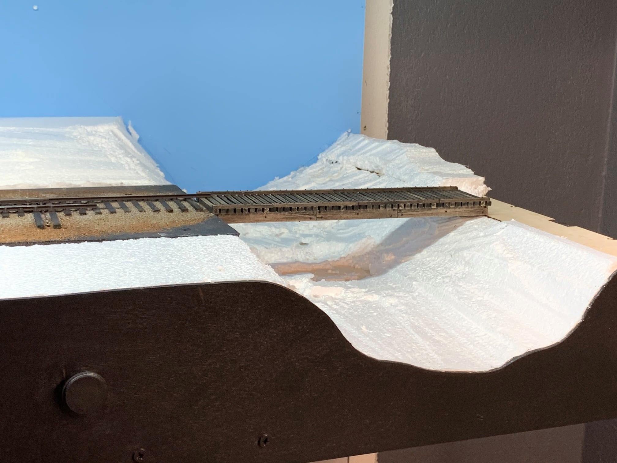
Most of my scenery techniques are from building dioramas over the years and since I am used to smaller scenery bases, this was a bit intimidating at first. For the scenery base, I used Styrofoam, plaster cloth and Scluptamold. Pretty standard on most modern dioramas and layouts. When the base was set, I painted everything with an earth color latex paint and allowed to completely dry.
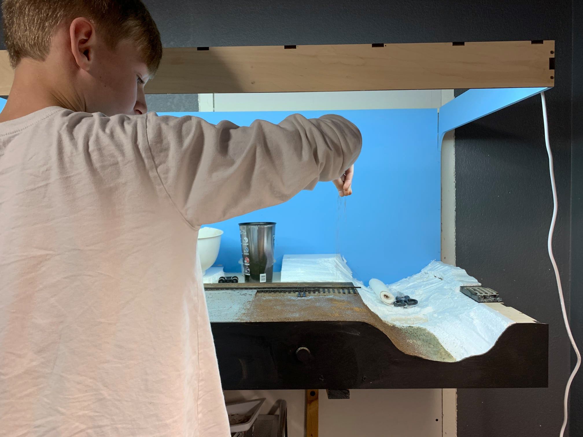
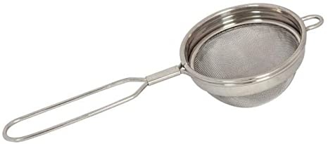
I am using dirt I collected in 5 gallon buckets from the angels camp area to make sure the ground cover is the correct color. The dirt is sifted into two selections: course and fine. A food strainer is used for course material while a tea strainer and sometimes even pantyhose is used for finer dirt.

I add a light coat to the scene, working in a small area at a time. I wet the area using a squirt bottle filled with water and a few drops of dish soap. White glue, diluted with water is then used to seal the dirt. As you may know, real dirt tends to darken when glued in place and as some modelers pointed out, grout added to the dirt helps keep its color. I’ve been experimenting with some non-sanded grout and trying to get the ratios correct for my soil.
The Bridge Deck
Now that the basic shape of the creek is roughed in, I turned my attention to the bridge. Since this is a freelanced railroad, I took my specifications from the Southern Pacific and Sierra Railroad. I started building the bridge before I received the module based on the dimensions. I had the bridge completed then assembled the module, however, my measurements were slightly off. Again, my problem with getting a bit too anxious in building got me again.
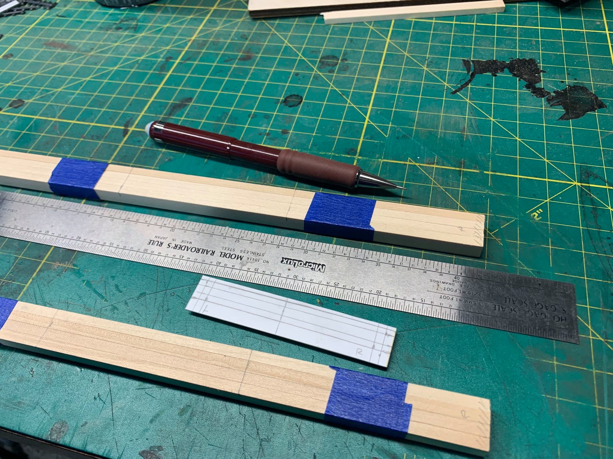
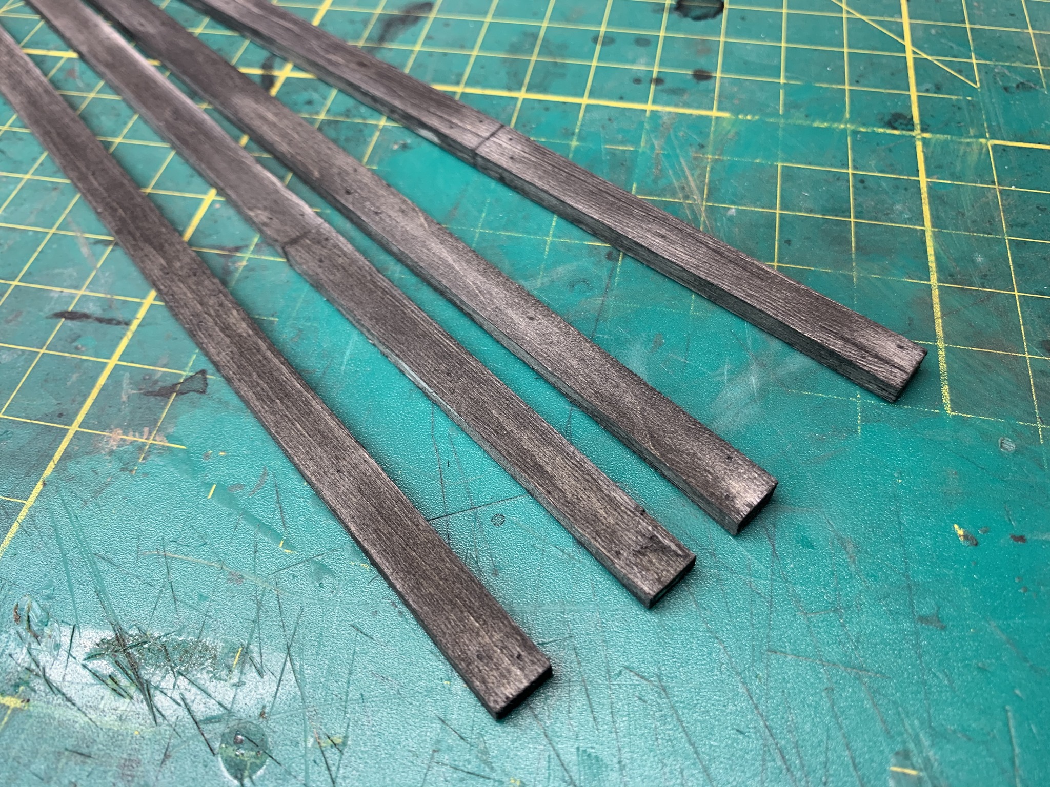
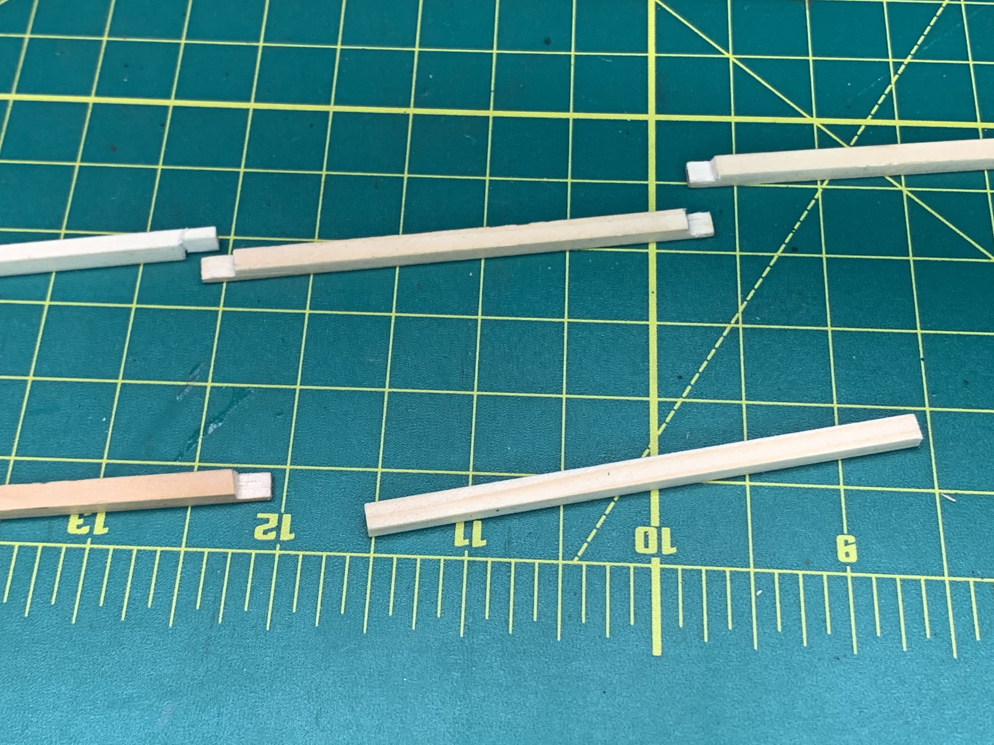
Although I am not keeping the model, I did learn a lot and was able to spend quite a bit of time researching trestle construction. I started by getting the actual measurements of the bridge location then cut the stringers to length.
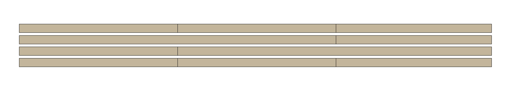
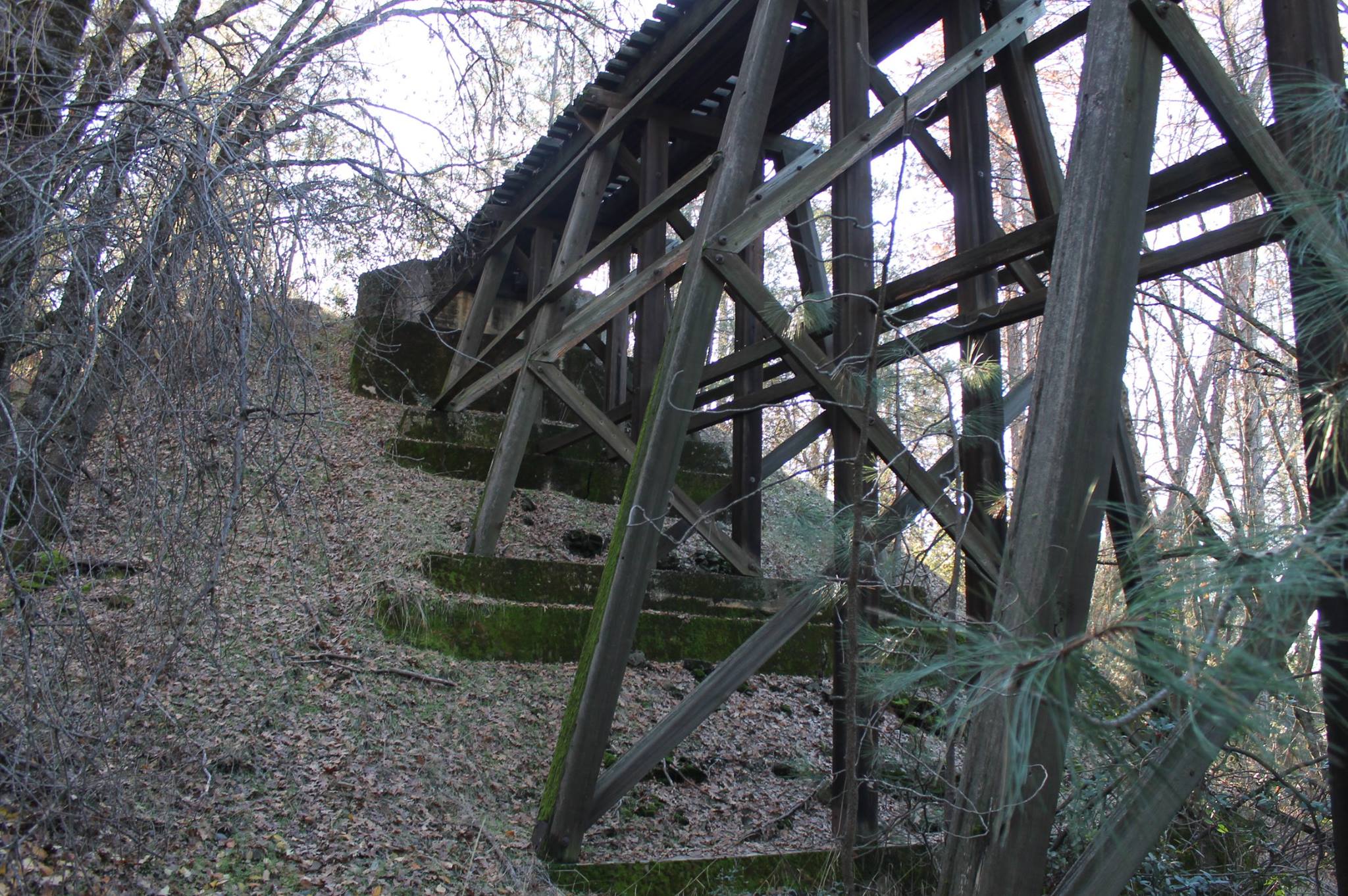
Although you would never see the stringer joints from the bottom, I chose not to off set them and score all joints in the same location to locate the bents. Studying the image above of Sierra Railroad’s Black Oak trestle, you’ll notice that they built it with four stringers and only four legs. Amazingly, this was strong enough to hold the weight of Mallet #38.
I decided to use four stringers as well, however I added an additional leg to the bents. Mostly because I like the look of five leg trestles but there are strength rating reasons to add the additional support as seen in this diagram.
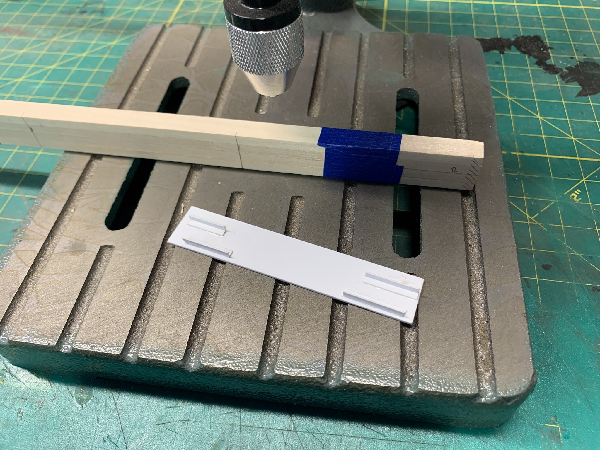
I created a drilling jig from styrene which was the length of the timbers. Using my workbench drill press, I was able to drill clean, even holes for the nut-bolt-washer details. These holes would also help me align the stringer spacers as you will see momentarily.
Once the holes are drilled, I began my weathering. Using a razor saw and a dull X-acto blade, I roughened the wood and added cracks and gouges.
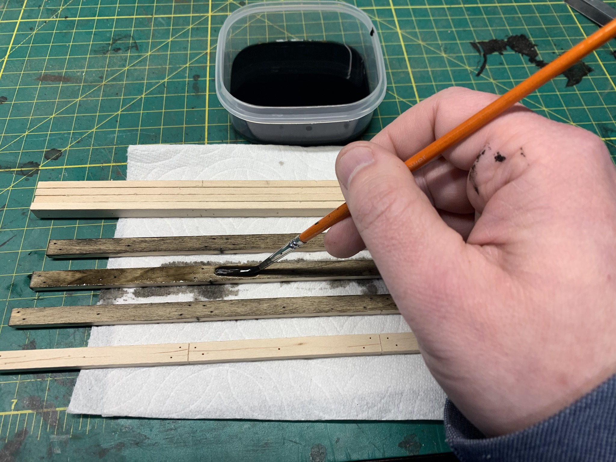
Weathering is done is several steps using black India ink and water. The ink is heavily diluted and applied in several coats.
Step 1. Stain each piece of strip wood
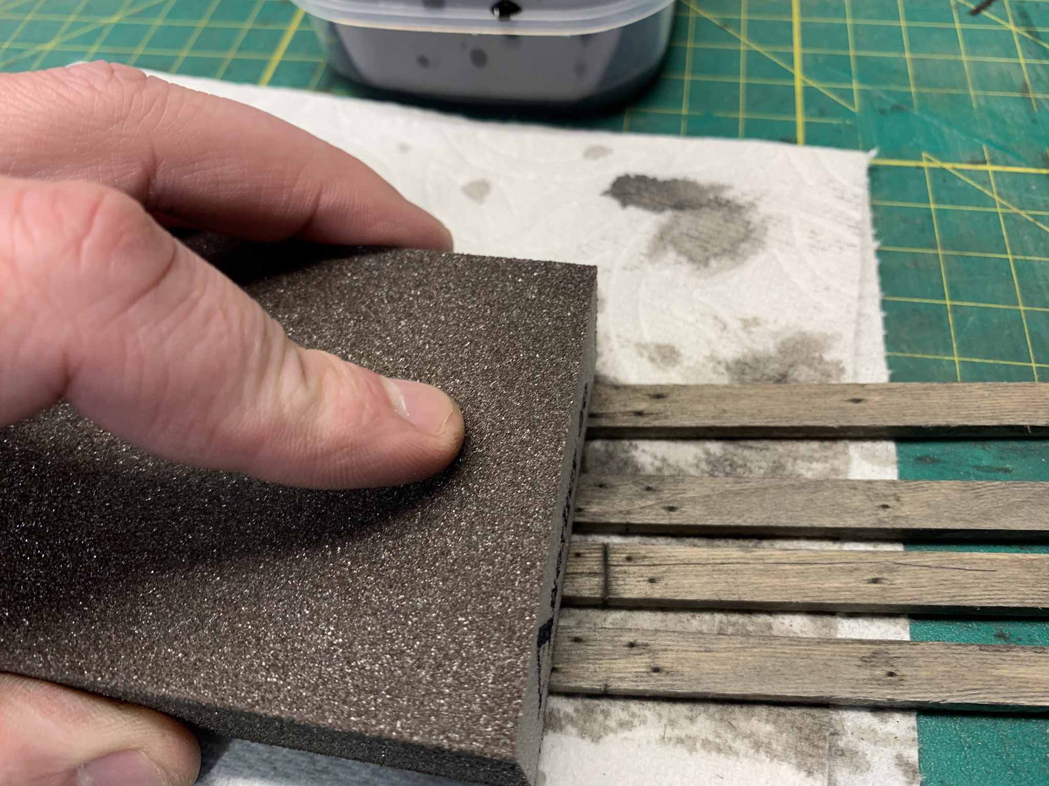
Step 2. Lightly sand some of the wood
Step 3. A couple of additional coats of the stain then sand again if needed and repeat the staining. I do this to create a uniform look to the color and highlight areas where the sun has begun bleaching the wood
Wood weathers differently around the world due to the environmental conditions. I would highly recommend that you research samples in the area you are modeling.
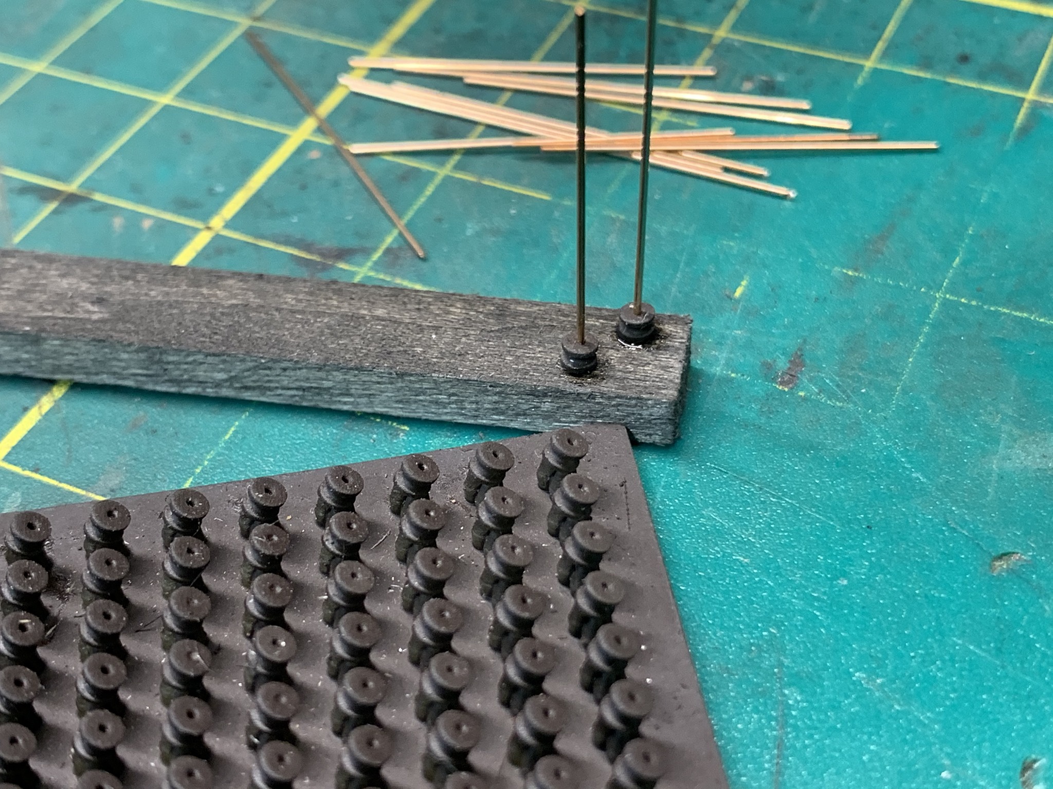
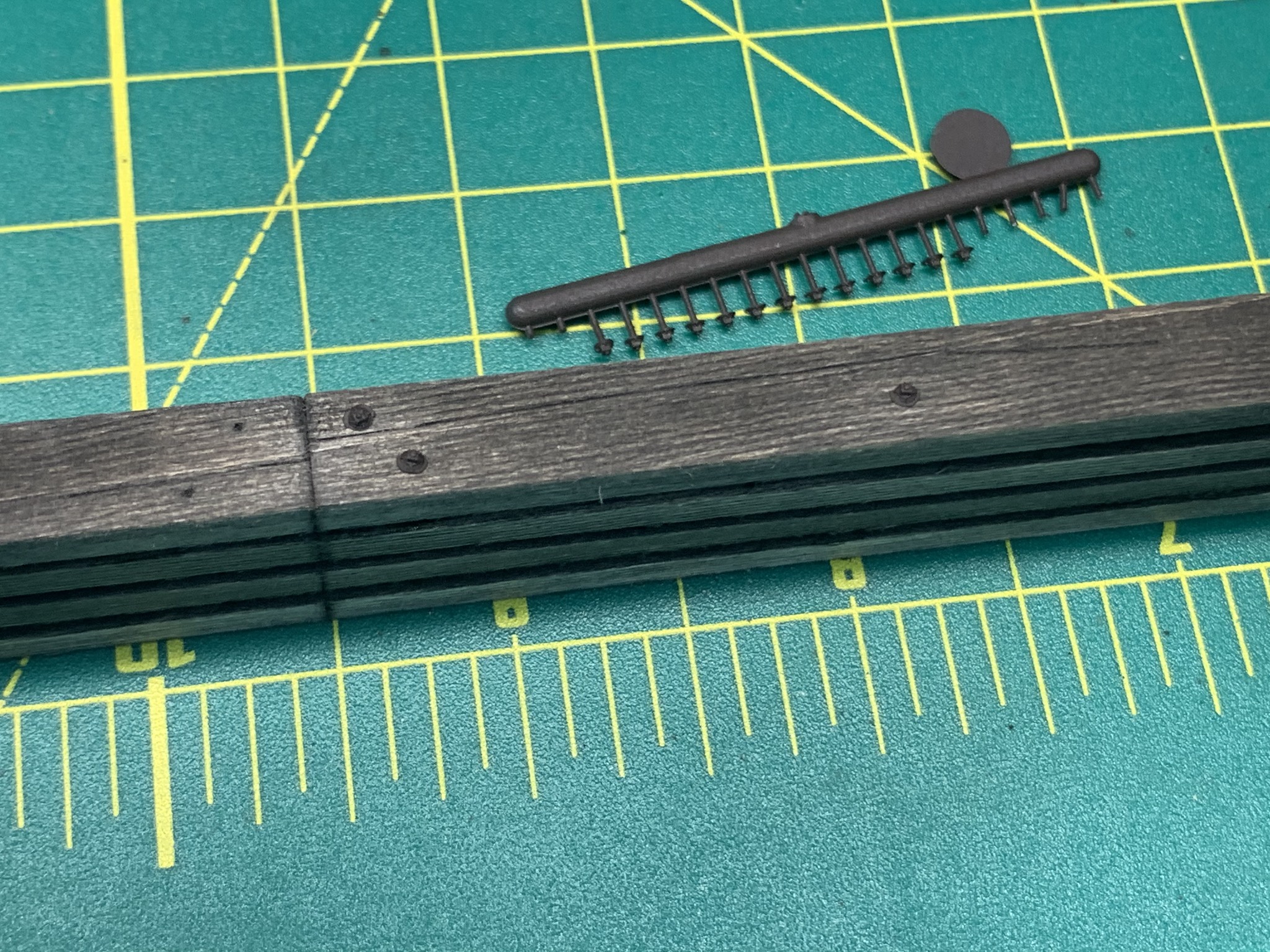
Normally I would use stripwood to space the stringers, however, I decided to add a bit of hidden detail in the stringers by using cast spacers. These were typically called washers and ranged in width from 1-inch to about 4-inches. Ed Traxler and I discussed 3D printing them and he was able to come up with a wonderful design. We decided to go with 2-inch spacers and they can be found on his MicroMimesis web site if you wish to purchase some yourself.
Using the holes I already pre-drilled, I cut a spacer off the sprue and inserted .020 wire from Tichy Train Group. CA was used to secure it in place. This part of the build is quite tedious and required quite a bit of patience but the results are worth it in my opinion.
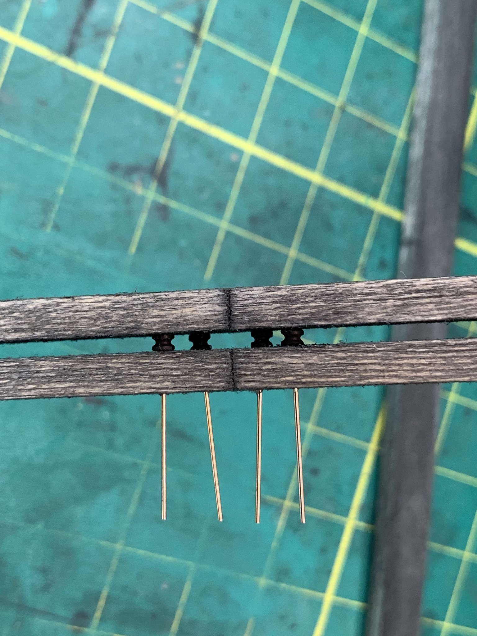
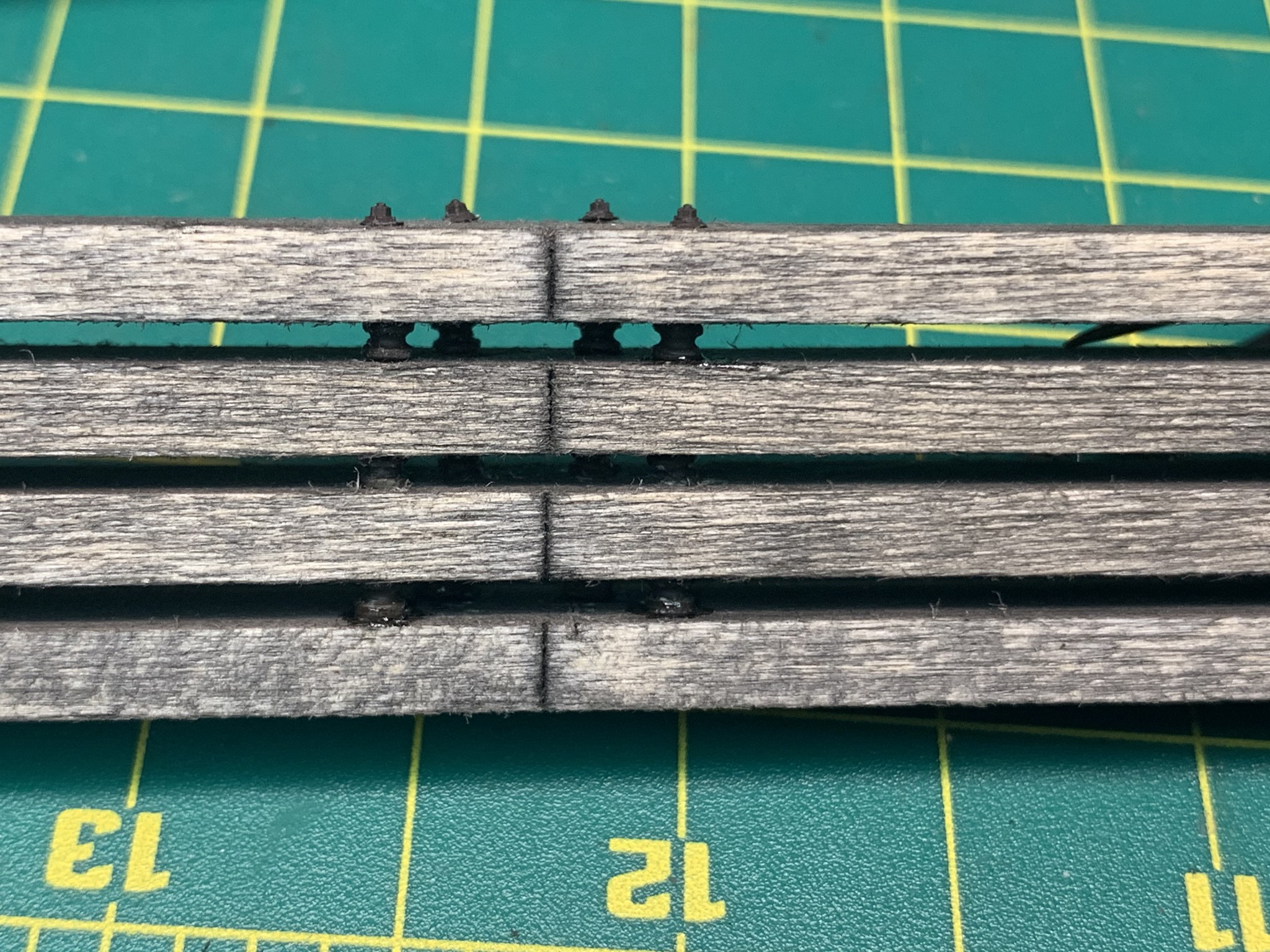
Once the spacers are dry, I begin adding my Nut-Bolt-Washer (NBW) details. Again, I use CA to secure everything in place.
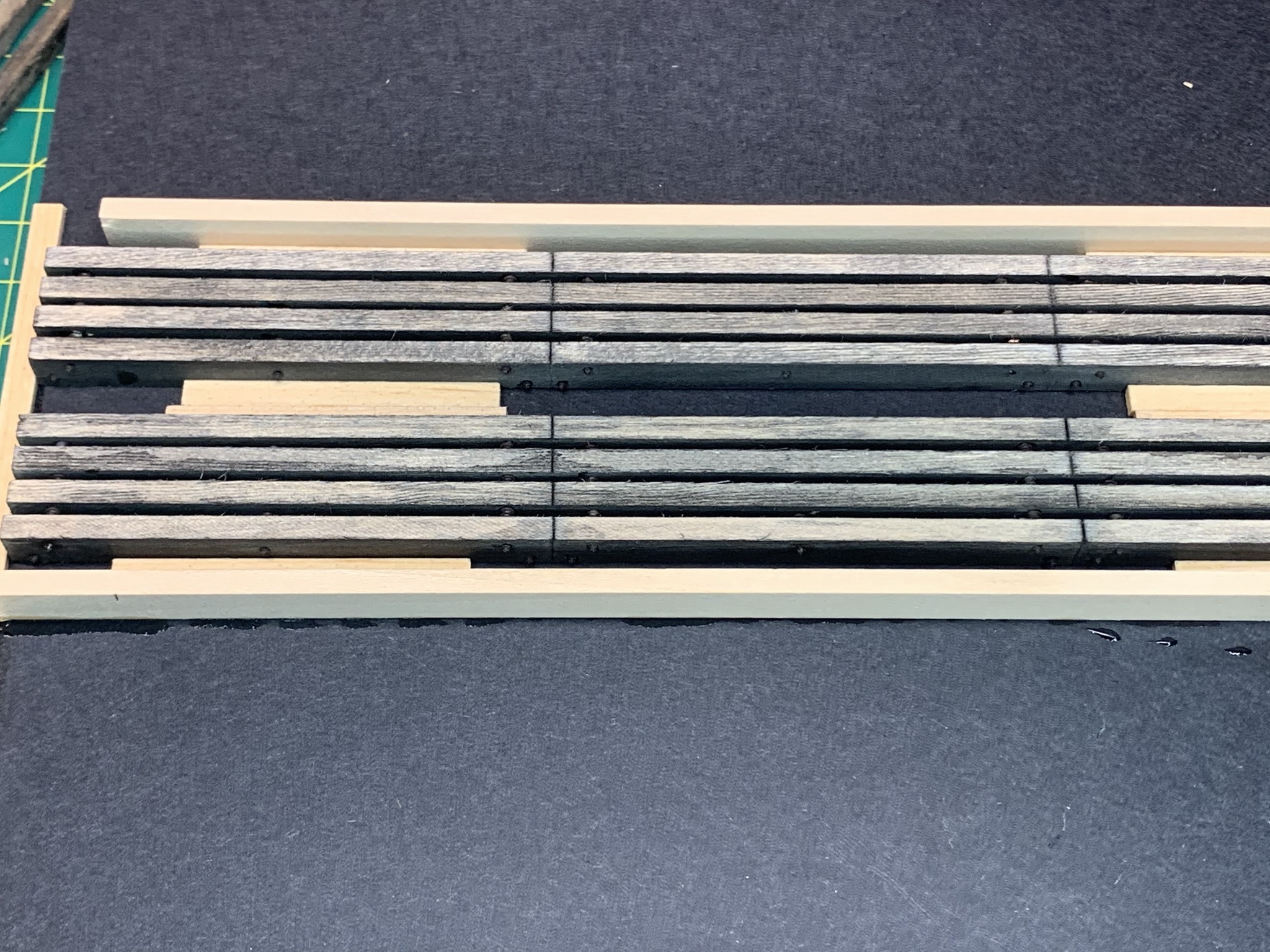
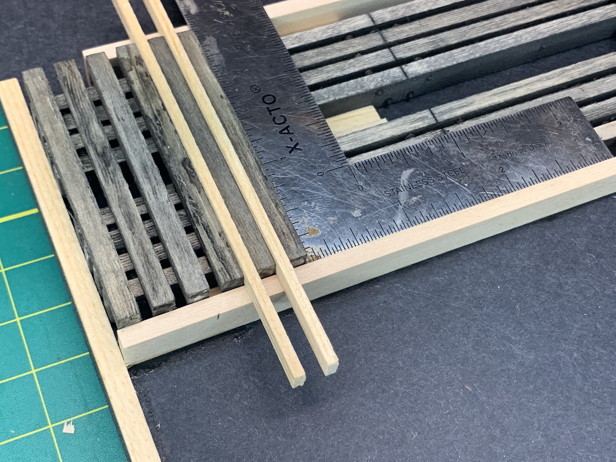
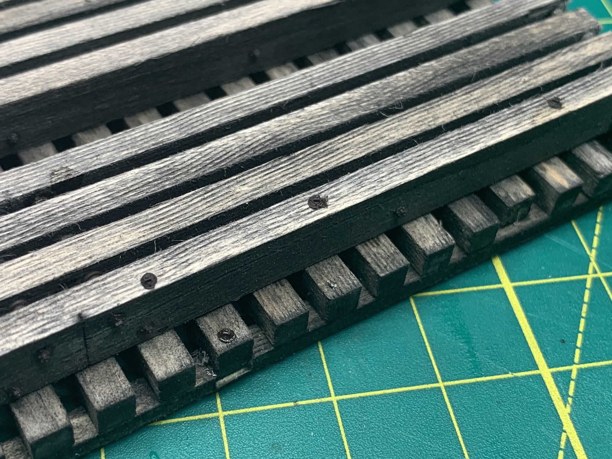
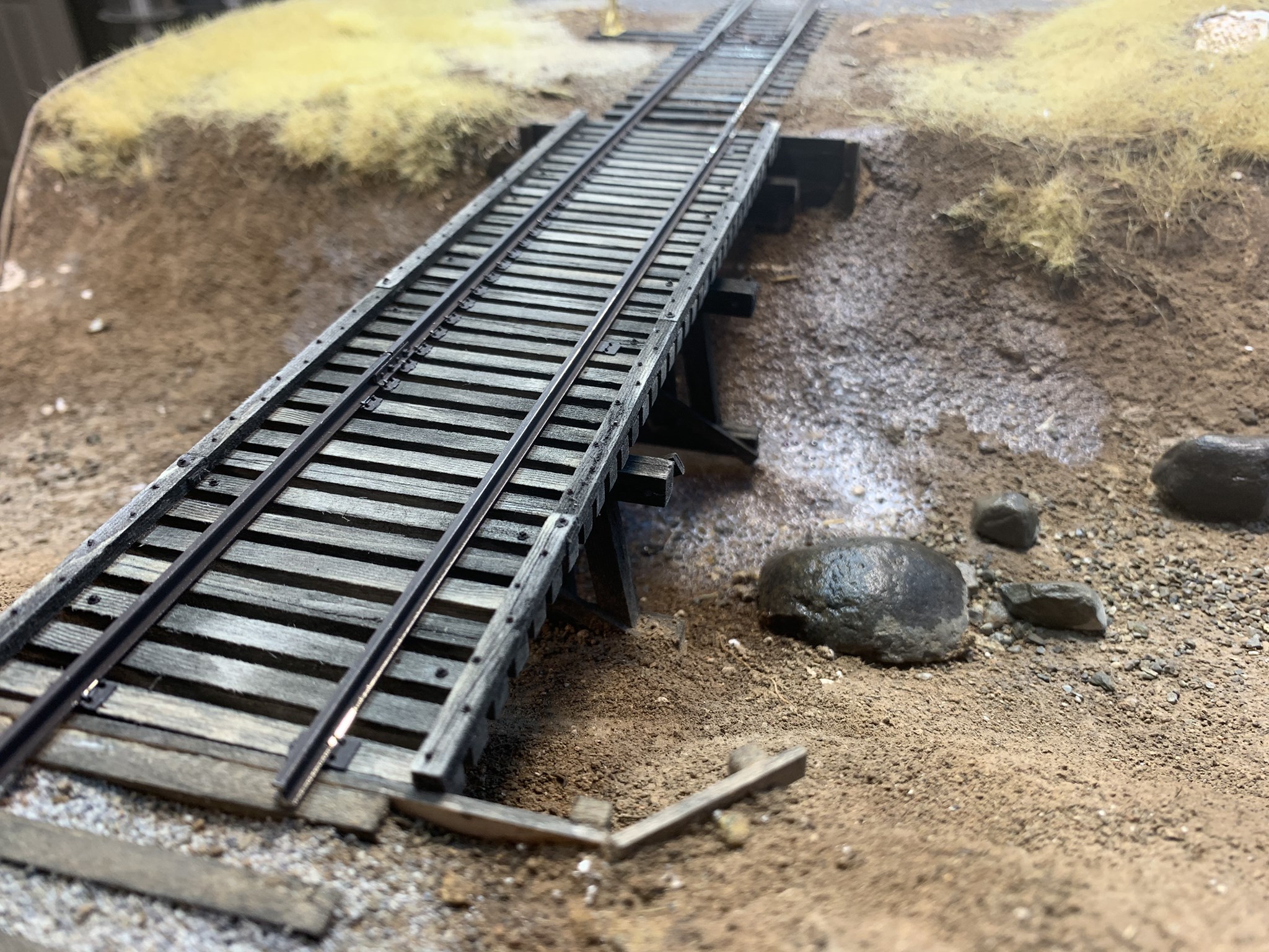
Now that the worst part of the build is over, construction went much faster. I built a jig using stripwood from my scrap box to secure the stringers and align the ties while I added them to the structure. I pre-stained the ties as I did the stringers and allowed them to dry completely. Then using a straightedge, I aligned the first tie, secured it in place with CA and allowed it to dry. The first alignment is critical otherwise all of your ties will be off and look terrible. Using stripwood, I then began adding the other ties, double checking square as I proceeded.
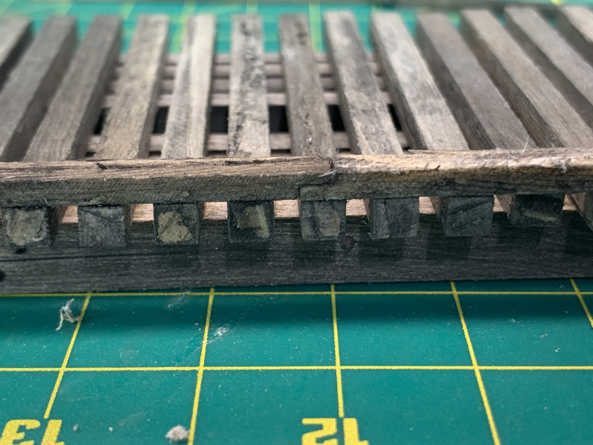
I then turned my attention to the timber guards. I notched them as per the prototype in order for the timbers to overlap and be bolted onto the ties. I then added grain details and stained them before glueing them into place.
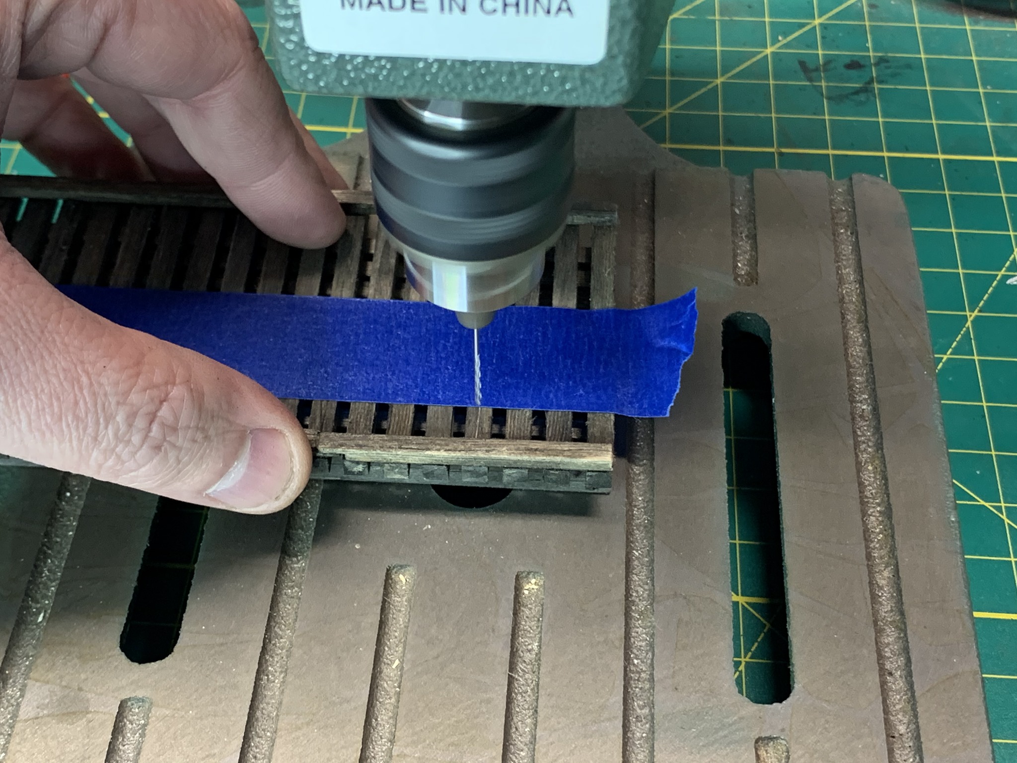
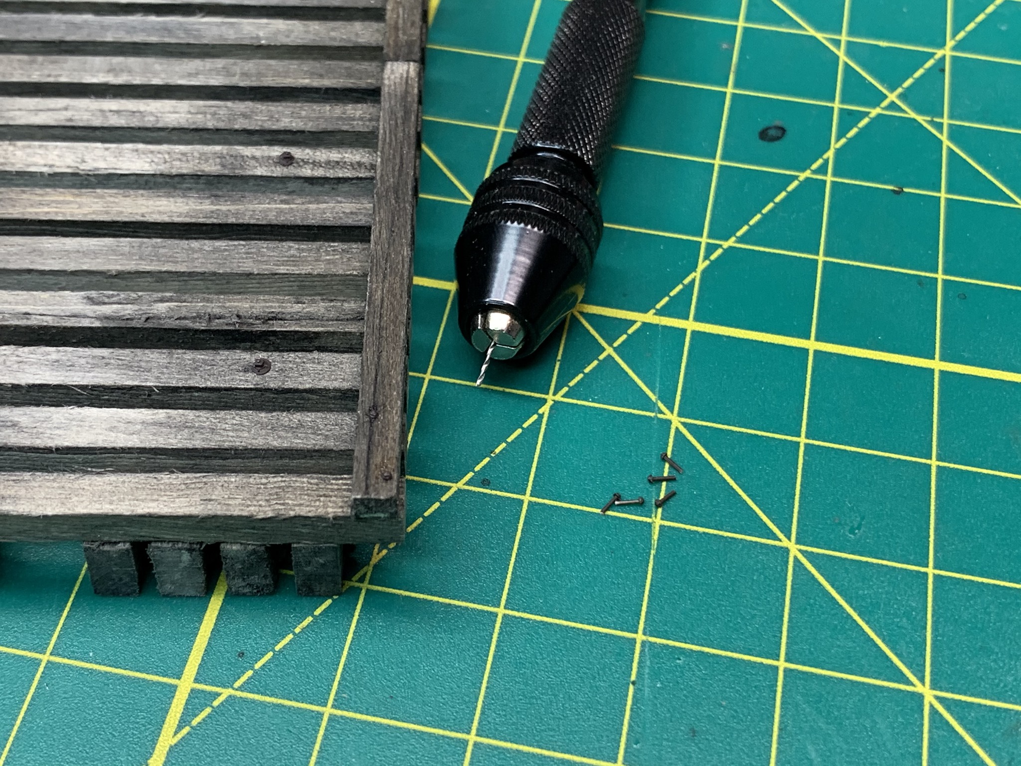
I’m using 2 methods for drilling the NBW details. The larger 2-inch bolts I am using my workbench drill press. For the nails, I’m using my hand drill. I use tape to align the holes for the bolts to attach the ties to the stringers. These are bolted on top and bottom and so the holes need to go all the way through. I also did the same for the guard timbers. The timbers are bolted to the ties at the timber joints while nails would be used to secure the timbers to the remaining ties. All of this detail was important for me to include since the shelf layout is small and all structures will be viewed up close.
It was amazing how much work I spent trying to figure out what type of abutments I was going to use and how they were built. Asking a lot of questions for fellow modelers on the Proto48 Group, there were a lot of retired engineers who helped with that information. I decided to go with wood timber abutments. I assembled them with the legs a bit long so I could trim them to the proper length when they were secured to the layout.
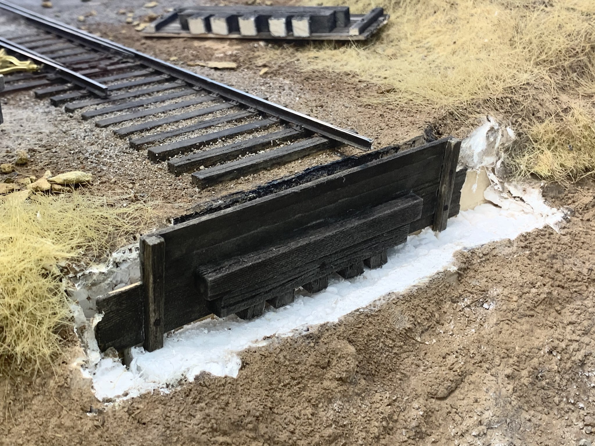
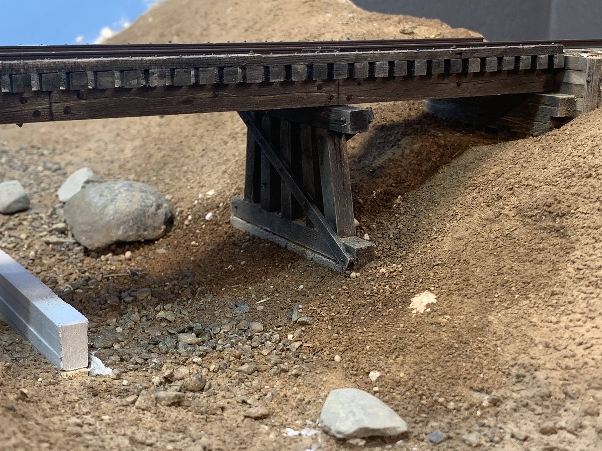
The abutments were attached to the layout with Liquid Nails adhesive. While the abutments were drying, I set the deck in place to make sure the timbers were at the right height and level.
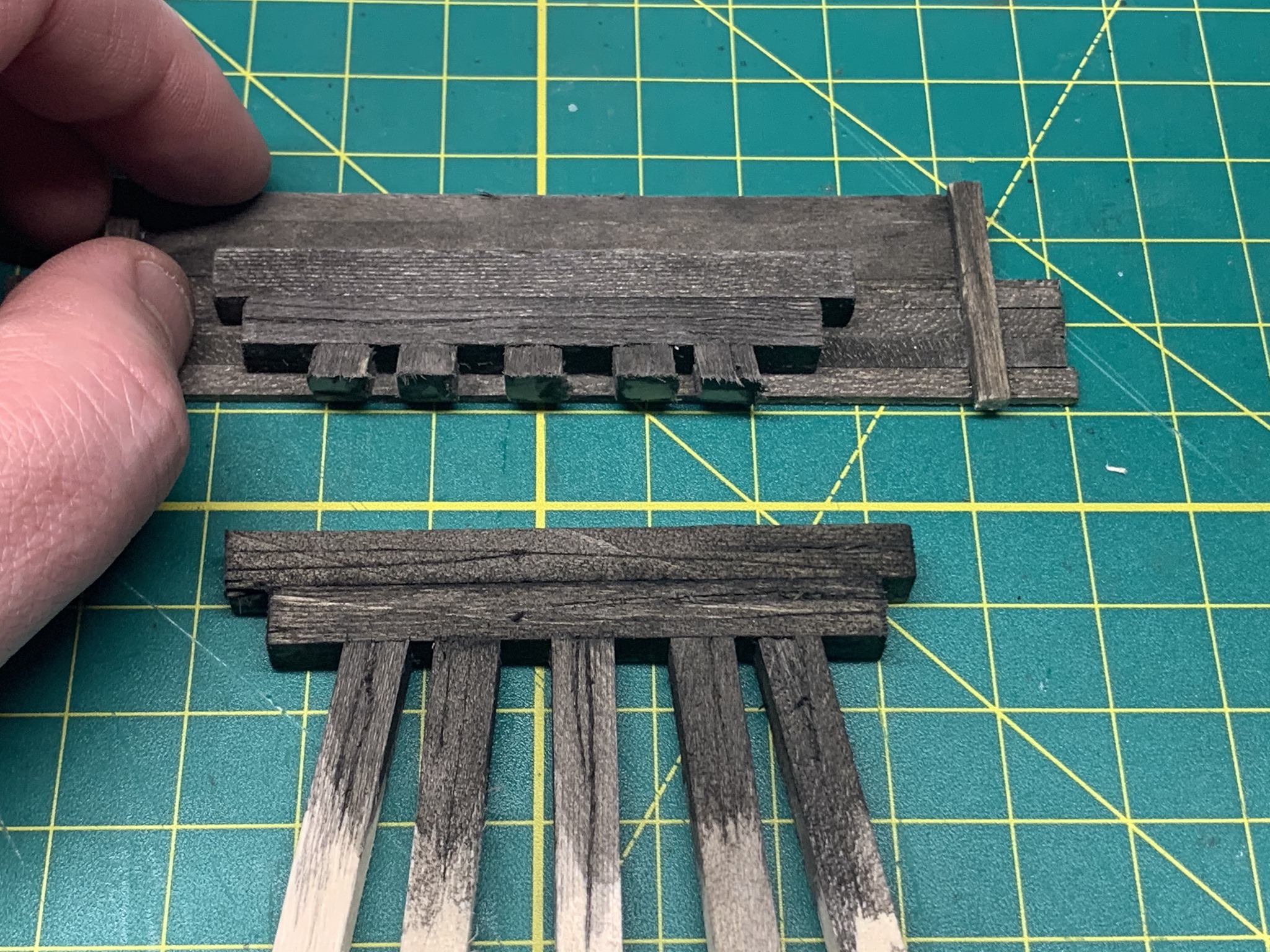
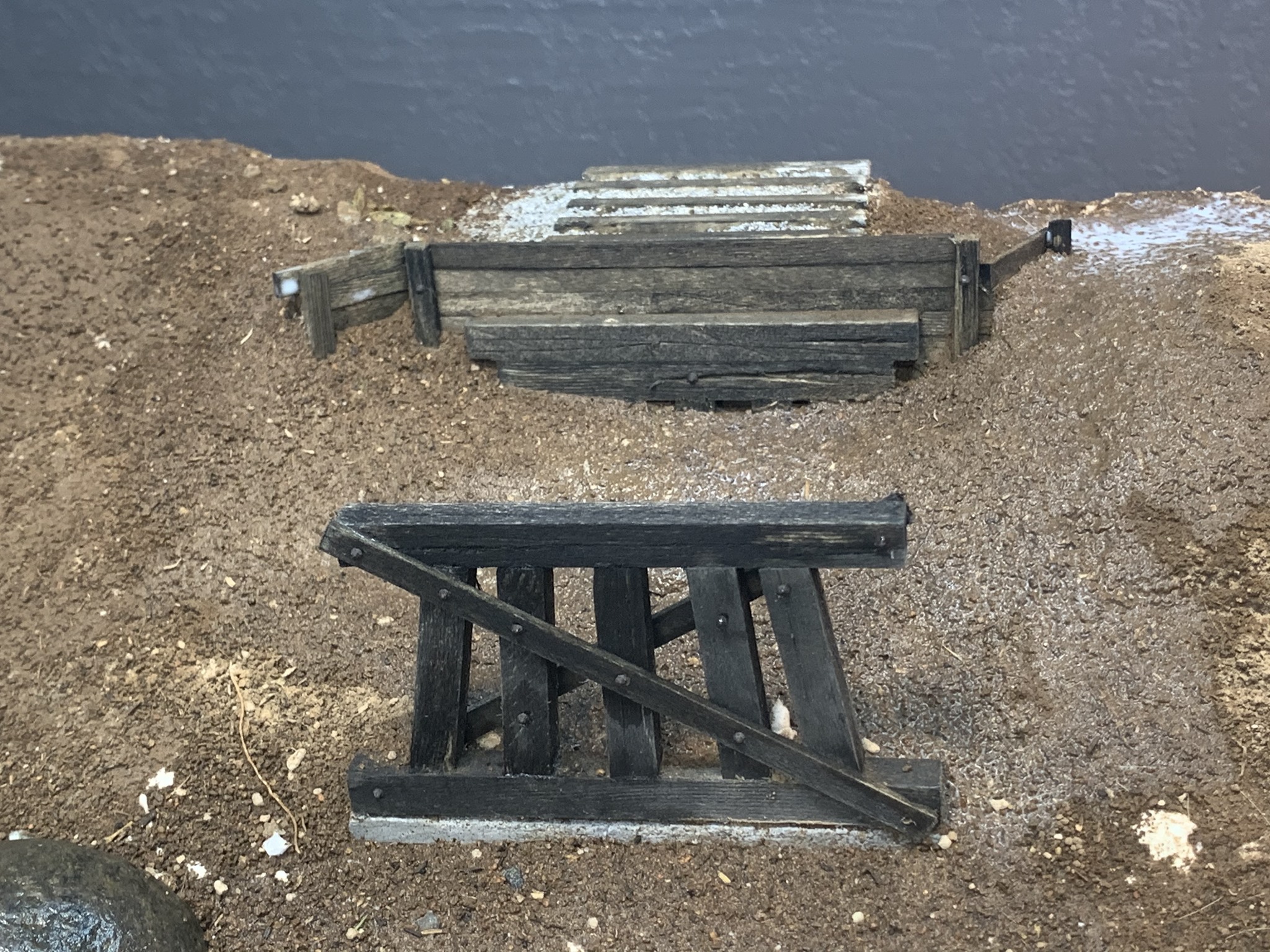
The Bents
I begin creating the bents by cutting the pieces to size and lightly pre-staining them. The legs were glued to the cap with CA and allowed to dry. After everything was dry, I trimmed the access material from the let and attached the sill.

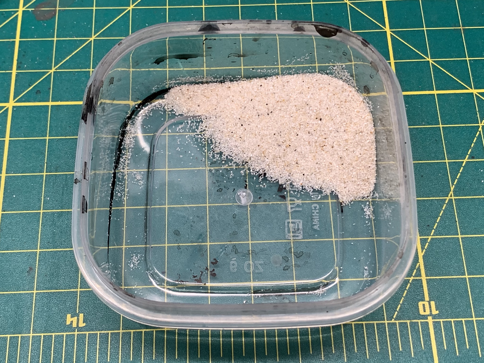
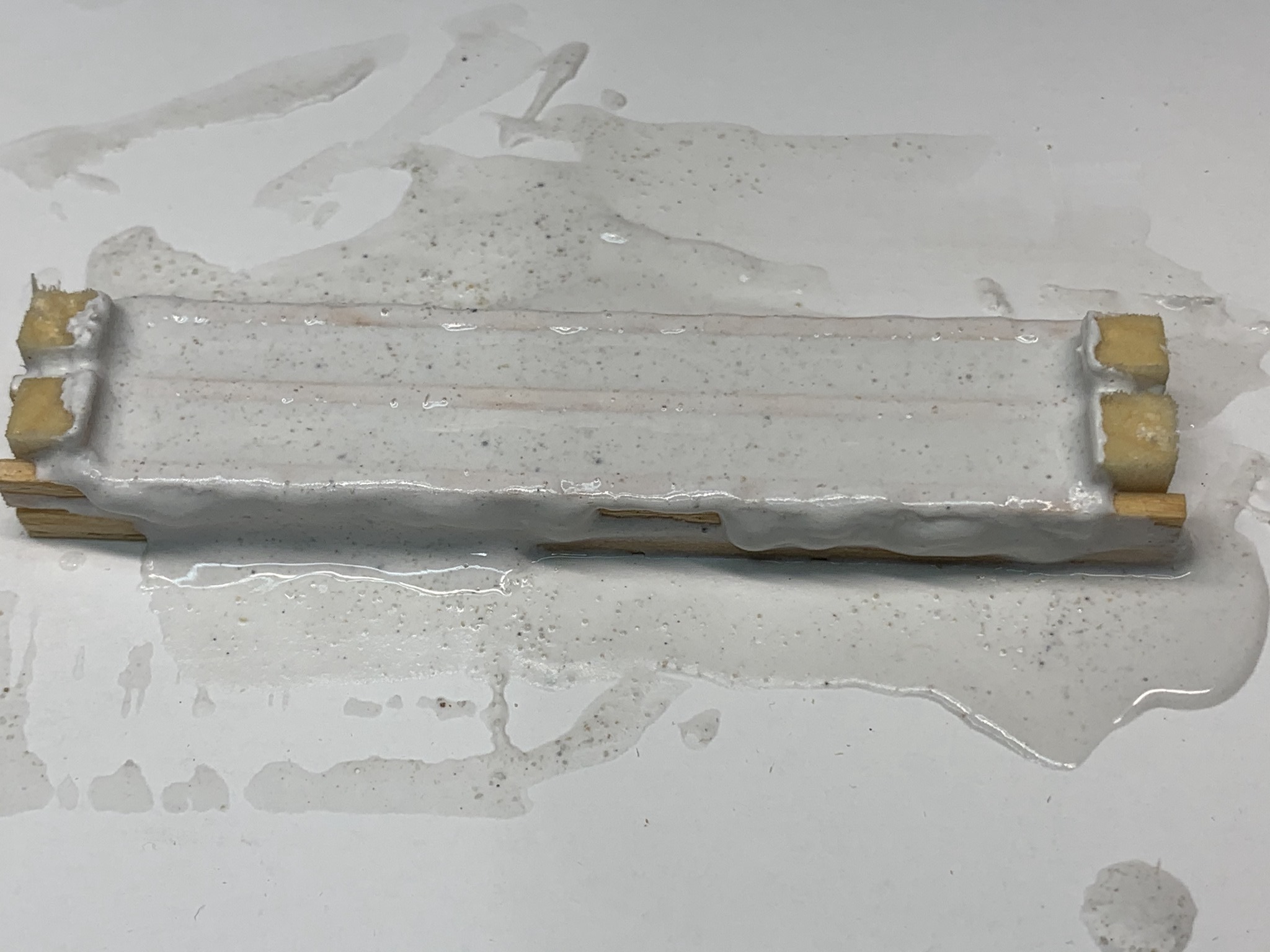
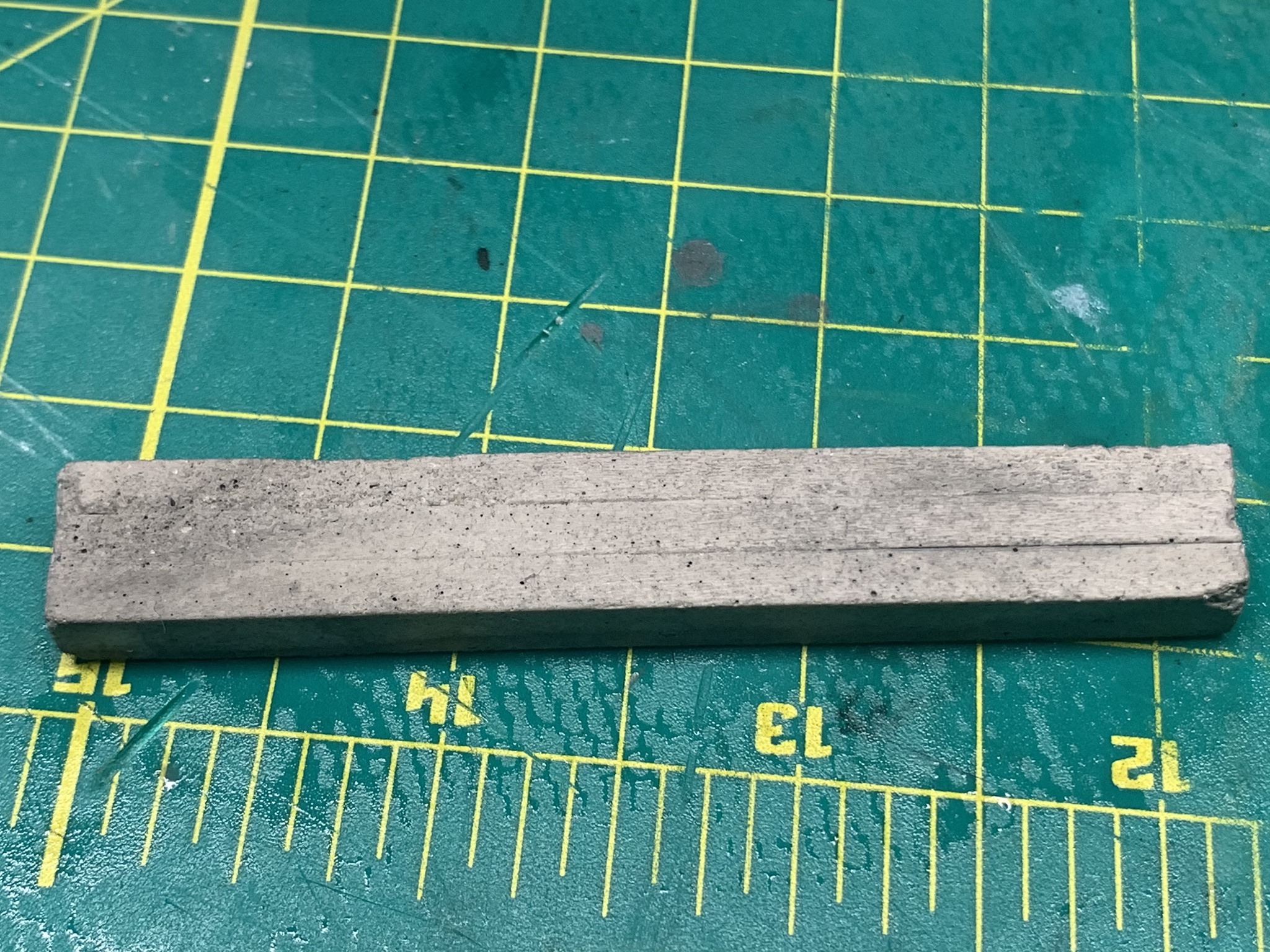
Next I moved on to concrete footings. I made a casting using stripwood which I distressed similar to the bents. I mixes extra fine sand and plaster, added a bit of flat black to add color and allowed to dry for 24 hours.
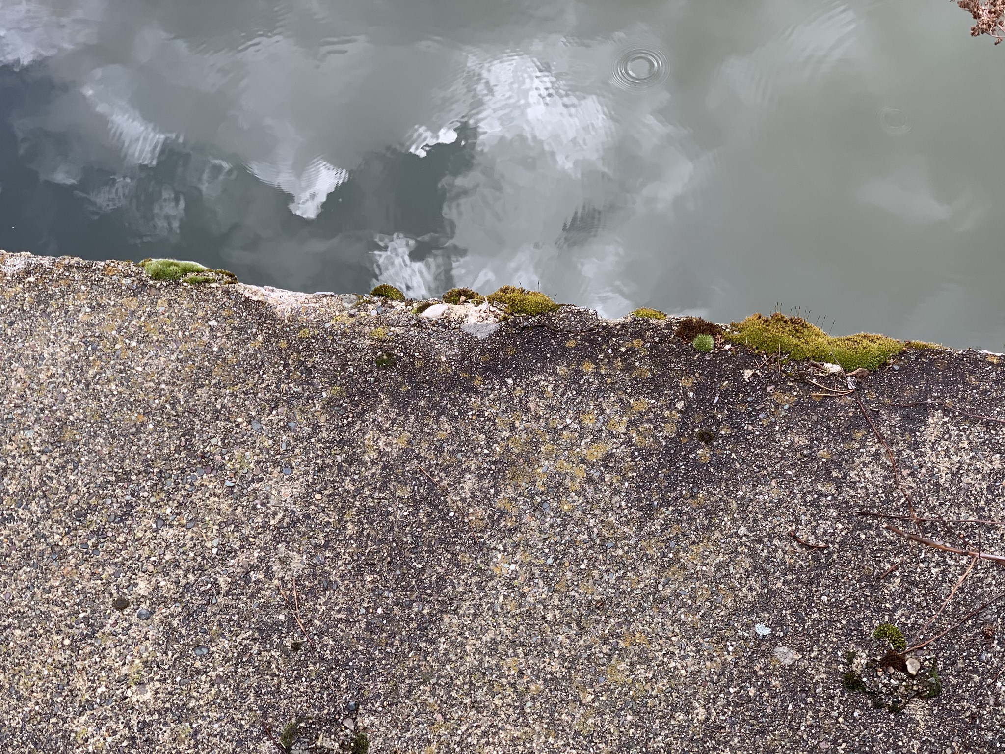
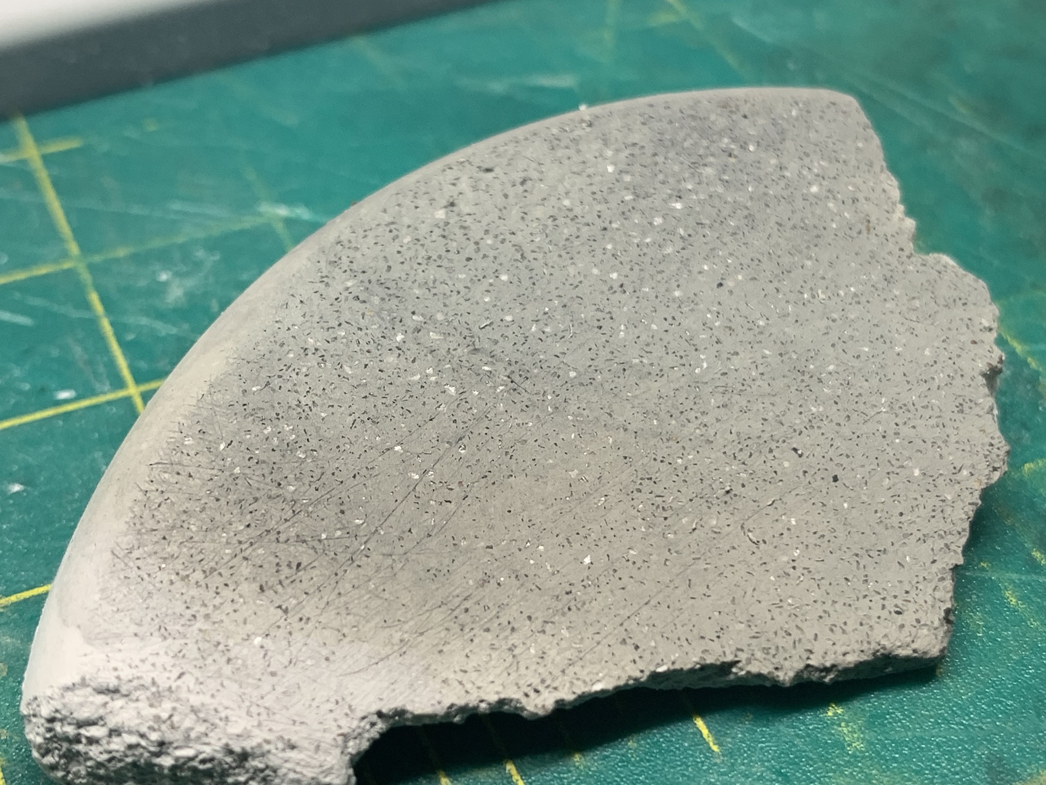
The molds were removed and the castings were set aside. Some of the remaining plaster was broken up and I used that to test some weathering techniques. I spent some time looking at prototype concrete to get an idea of colors and textures. I used the image below as a guide.
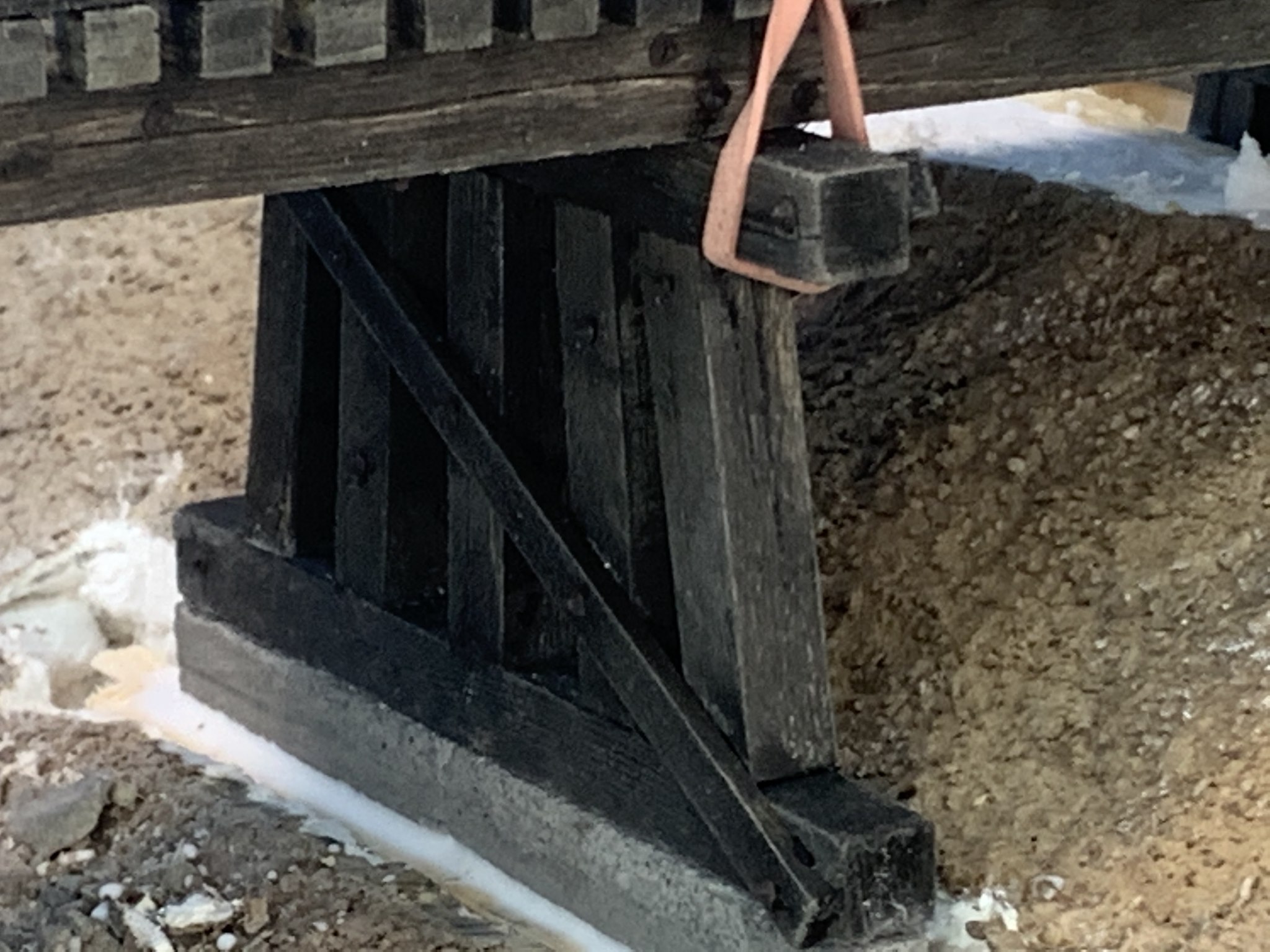
I used a wire brush to scratch the surface and expose the aggregate. I followed that up with a wet paper towel to smooth the surface. I mixed Woodland Scenics acrylic aged concrete with just a touch of flat black. This was heavily diluted and applied with a paper towel. I was happy with the results as a base. Once the footings are in place I will finish weathering to look more like the prototype photo below.
As noted before, I had already added the basic land forms so I needed to cut out foundations for the bents.
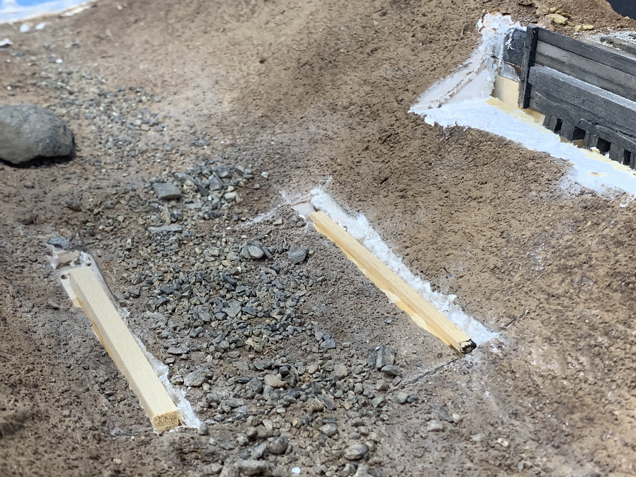
The bent was set in place and white glue used to set it in place and allowed to dry for 24 hours. I followed that with dirt and glued that in place.
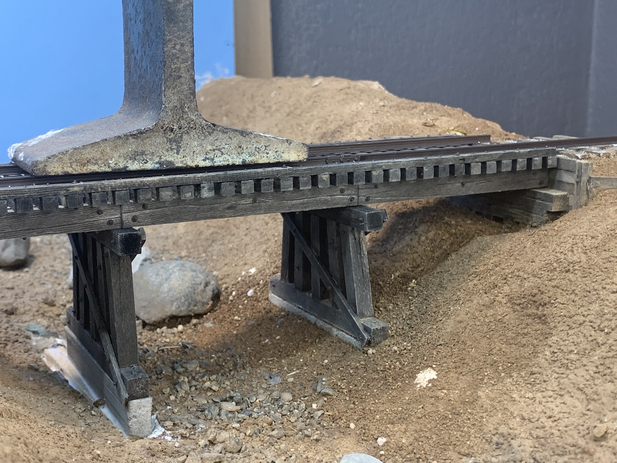
The second bent was built and installed the same way. Again, I allowed it to dry and added dirt to the scene and set that in place.
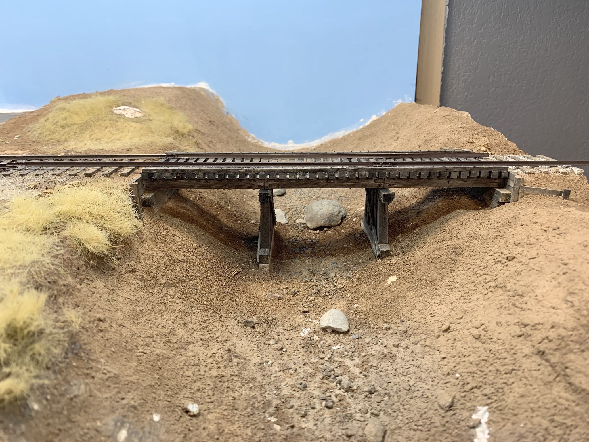
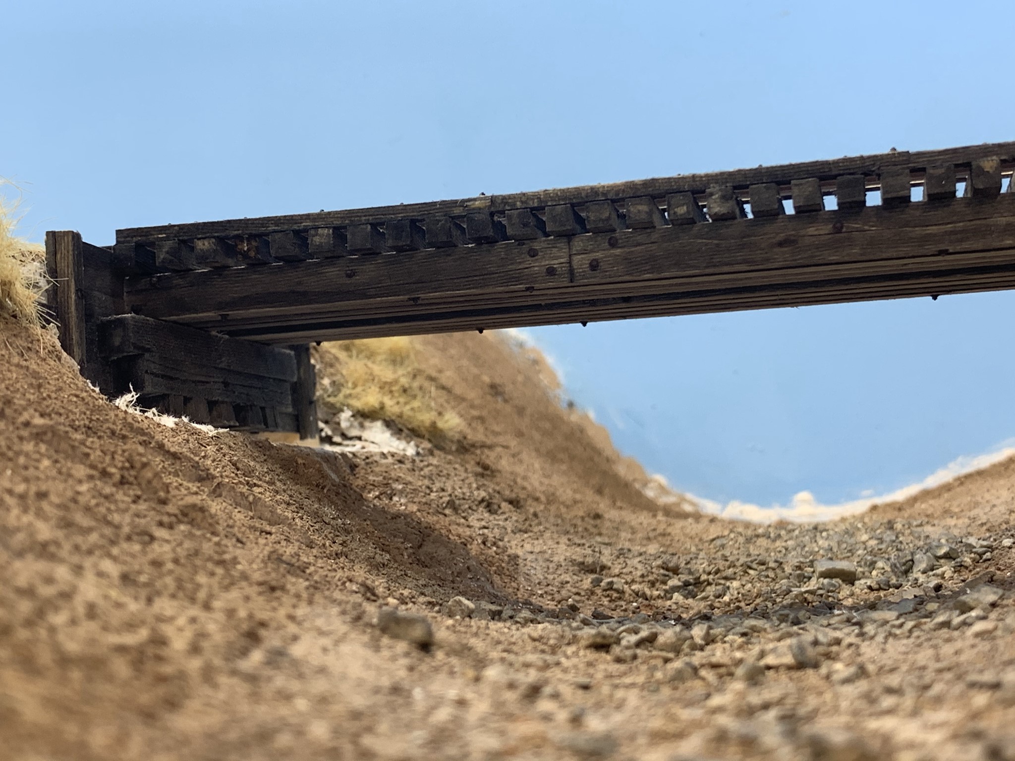
All that is left now is to complete the rail and finish weathering. I am very happy with how this model turned out and I very much appreciate all the input to guide my research. Hopefully I will be able to get to the creek bed and vegetation soon. For now, work will continue on the main line.

Very nice. I like seeing all the jigs you came up with to assist the project. The result is fantastic.
I appreciate it Greg! I’m quite proud of this build.
That is outstanding work
Thank you Joe!
Amazing work! You’re a real inspiration.
Thank you very much Sean!
[…] of the highlights of my Sierra Pacific Railroad is Angels Creek and the trestle crossing on the railroad’s main line. Although the railroad is freelanced and headquartered […]
[…] of the highlights of my Sierra Pacific Railroad is Angels Creek and the trestle crossing on the railroad’s main line. Although the railroad is freelanced and headquartered in […]