A while ago, Jay Criswell, owner of Right O’ Way, approached me and mentioned he was designing a new switch kit in both standard O scale (Ow5) and Proto48. He mentioned he was teaming up with Brad Strong from Signature Switch Co. to produce a switch that would be easy to assemble for both the novice and experienced model builder. Jay explained these switches would utilize Right O’ Way details with the expert track building of Brad. I was intrigued.
Well, Brad and Jay completed a prototype of both a number 6 switch in code 125, and with an acrylic template for placing ties and locating the track. I was asked if I would assemble the prototype and jumped at the opportunity. With that in mind, I thought I would share my experience of the build along with additional tips and tricks to speed up your build.
The Kit
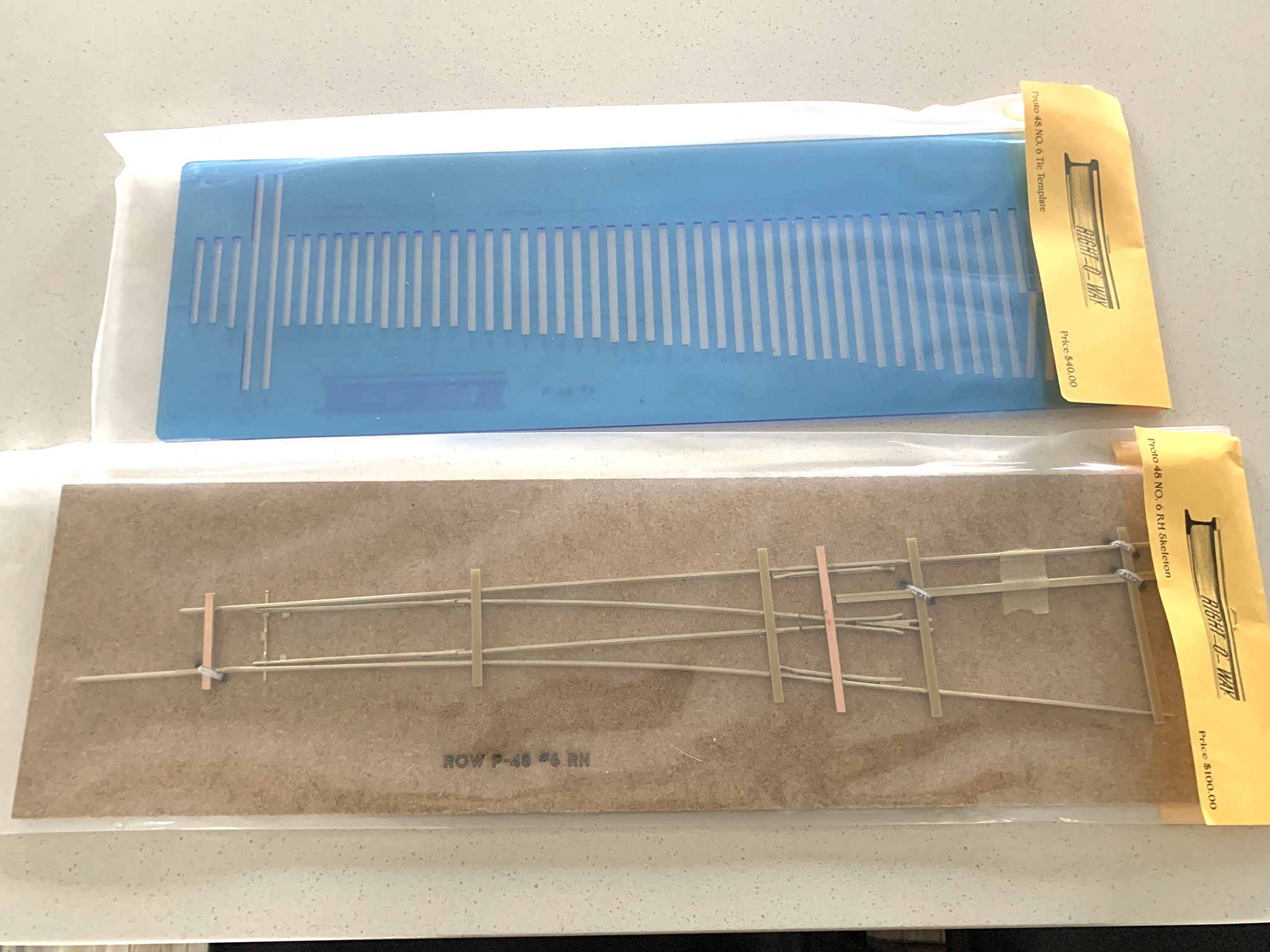
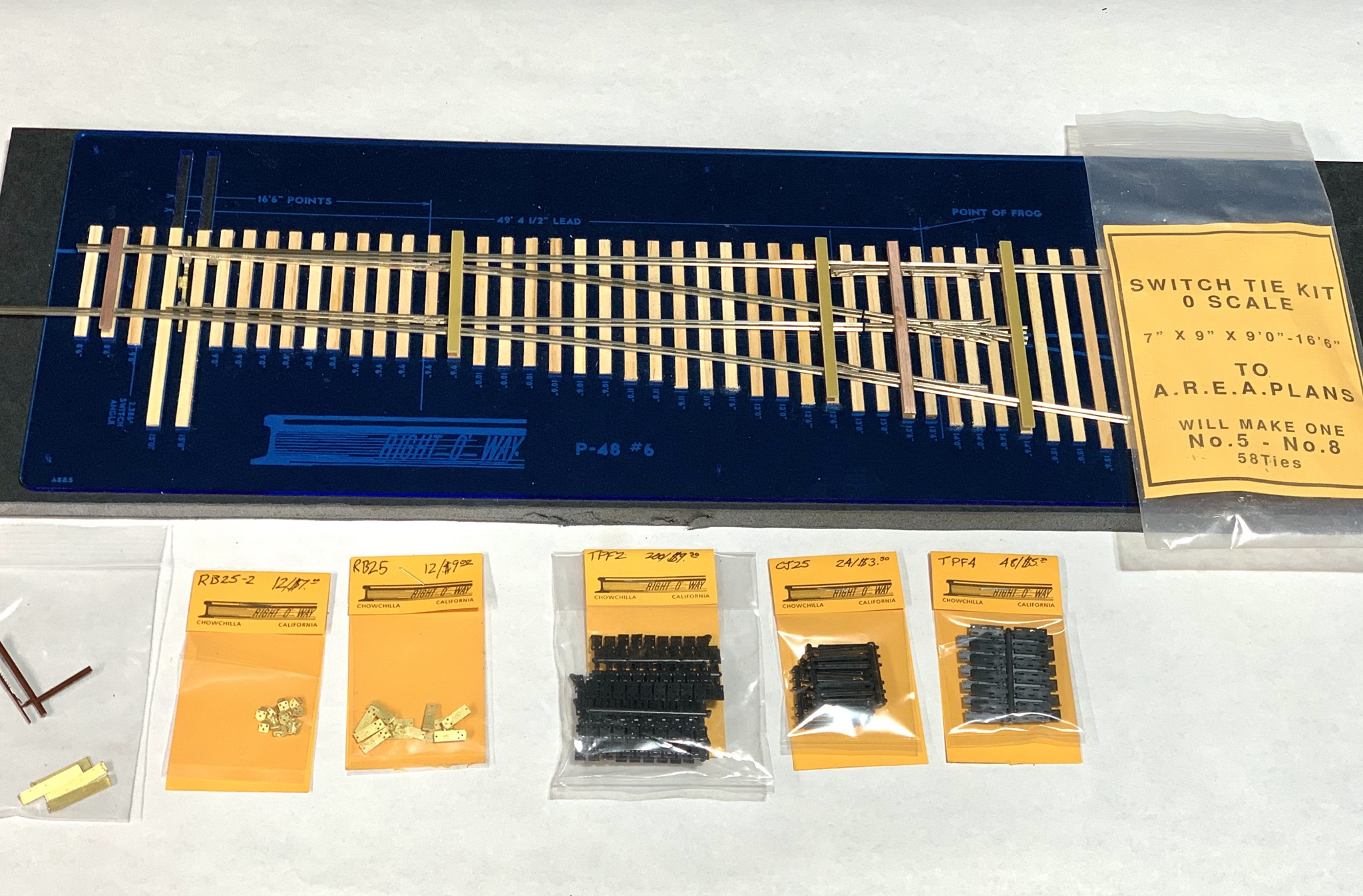
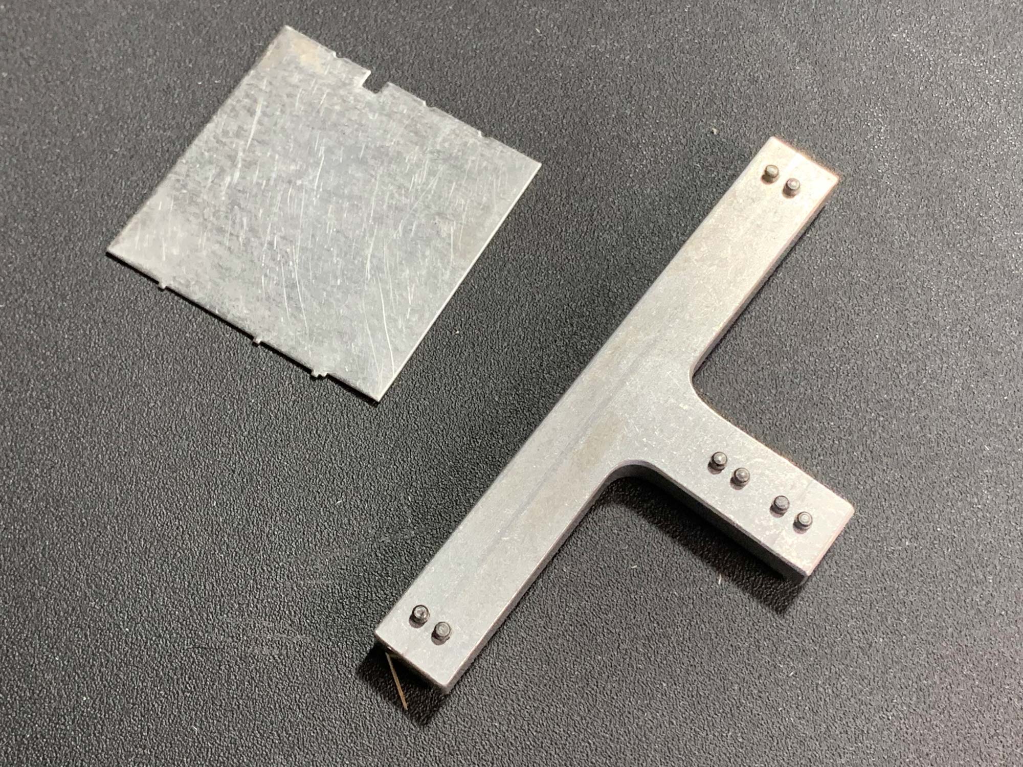
There are two separate products included in this article; the acrylic tie jig and the switch kit. Along with the switch kit, Jay provided extra details, which included; Gauge Plates, Rail Braces (with no tie plates), Rail Braces (with tie plates), Code 125 Tie Plates, 24″ Flat Tie Plates, and Code 125 Rail Joiners. The switch itself already has a bolted style frog in place along with 16′ – 6″ switch points. Both are cast in nickel silver and loaded with cast-on details. The list of components may change before the production kit is complete, so please contact ROW for more detail.
Laying the Ties
Typically, I would roughen and weather the ties before I glue them in place, however, the switch is intended to be displayed so we decided to leave it unfinished to show off the parts.
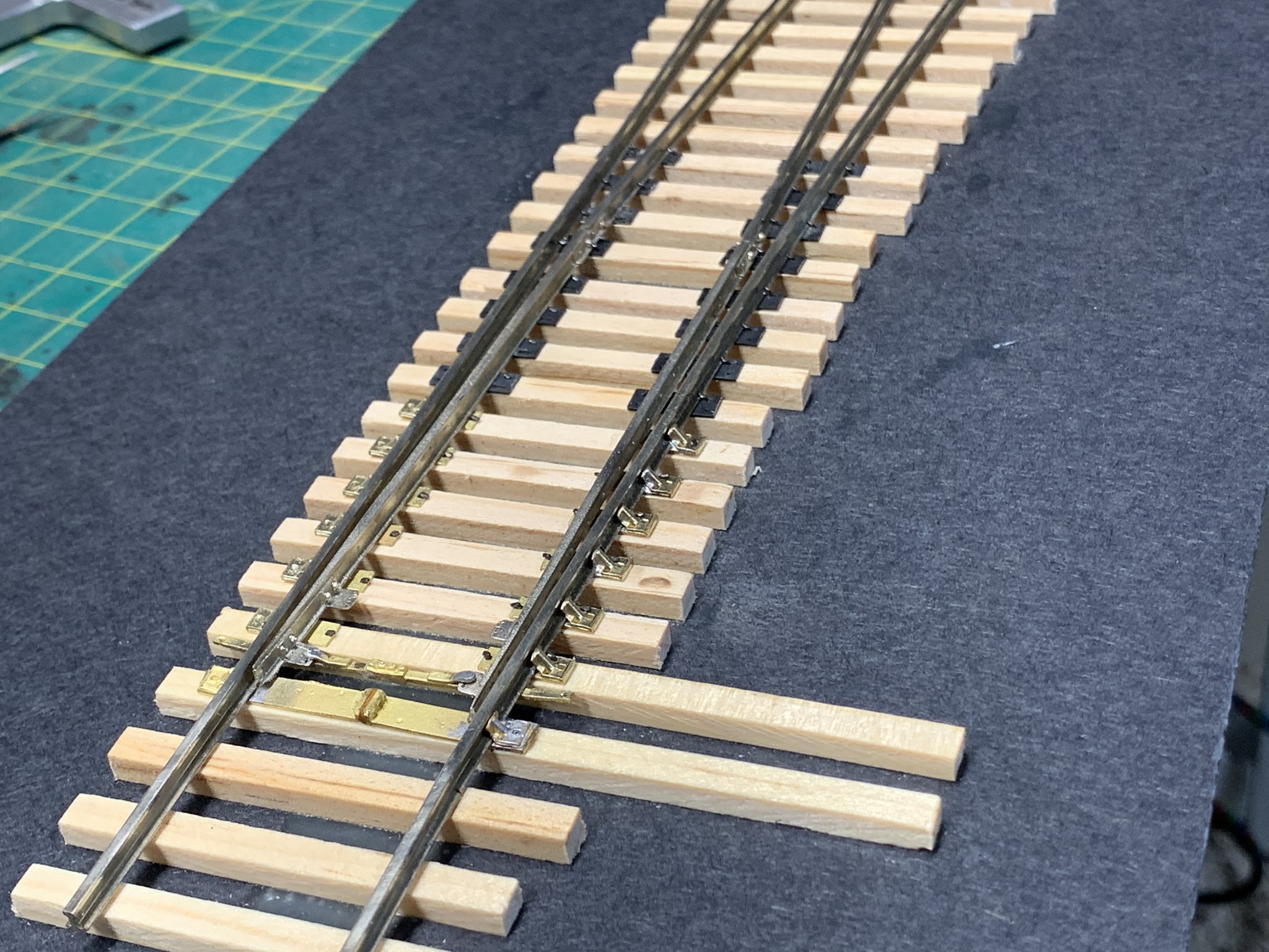
I set the ties into the tie jig and marked the rail locations on the end of the ties. I then used painter’s tape to secure the tie so I could remove them from the jig.
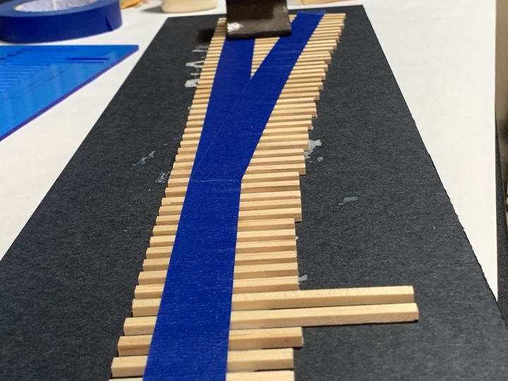
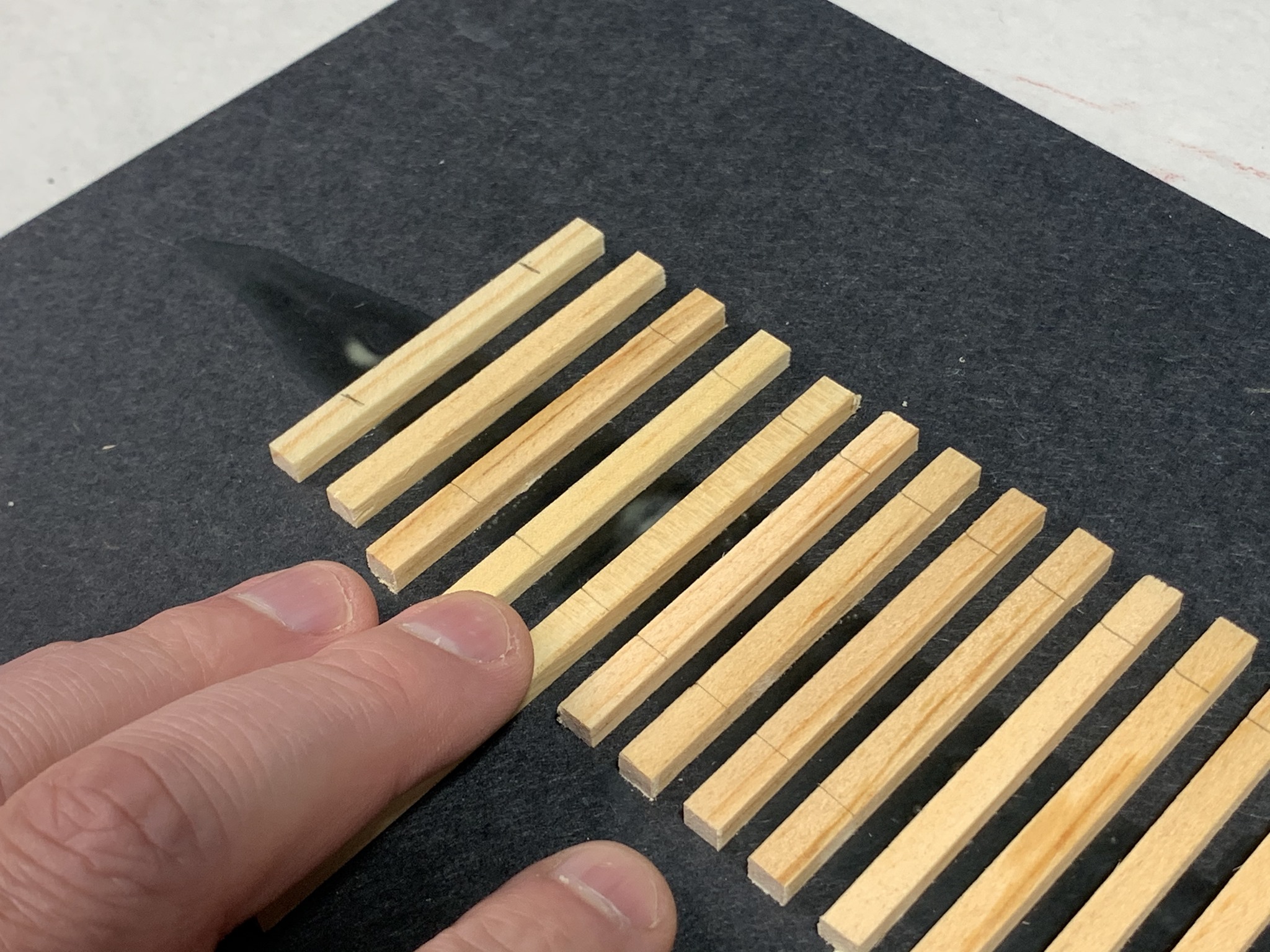
Wood glue was spread onto the base and the ties were set in place. Once the glue was dry, I finished marking the ties to place the rail in the correct location.
Laying the Switch
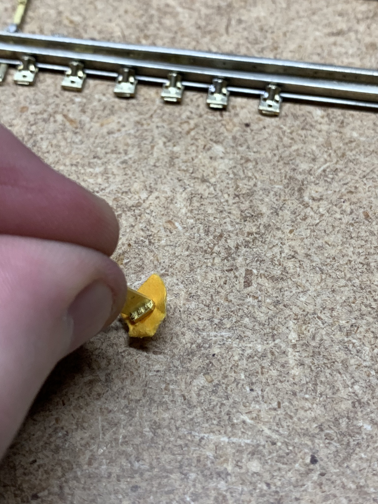
The switch is completely isolated so the modeler can run DC or DCC depending on their preference. Normally when I hand lay track, I focus on one rail at a time, however, since these are already assembled, I had to improvise and discovered a couple new techniques I found useful. As with all my switches, I like to solder the brass details to the rail when appropriate. Not wanting to be wasteful, I put the ROW labels that were attached to the detail parts to good use.
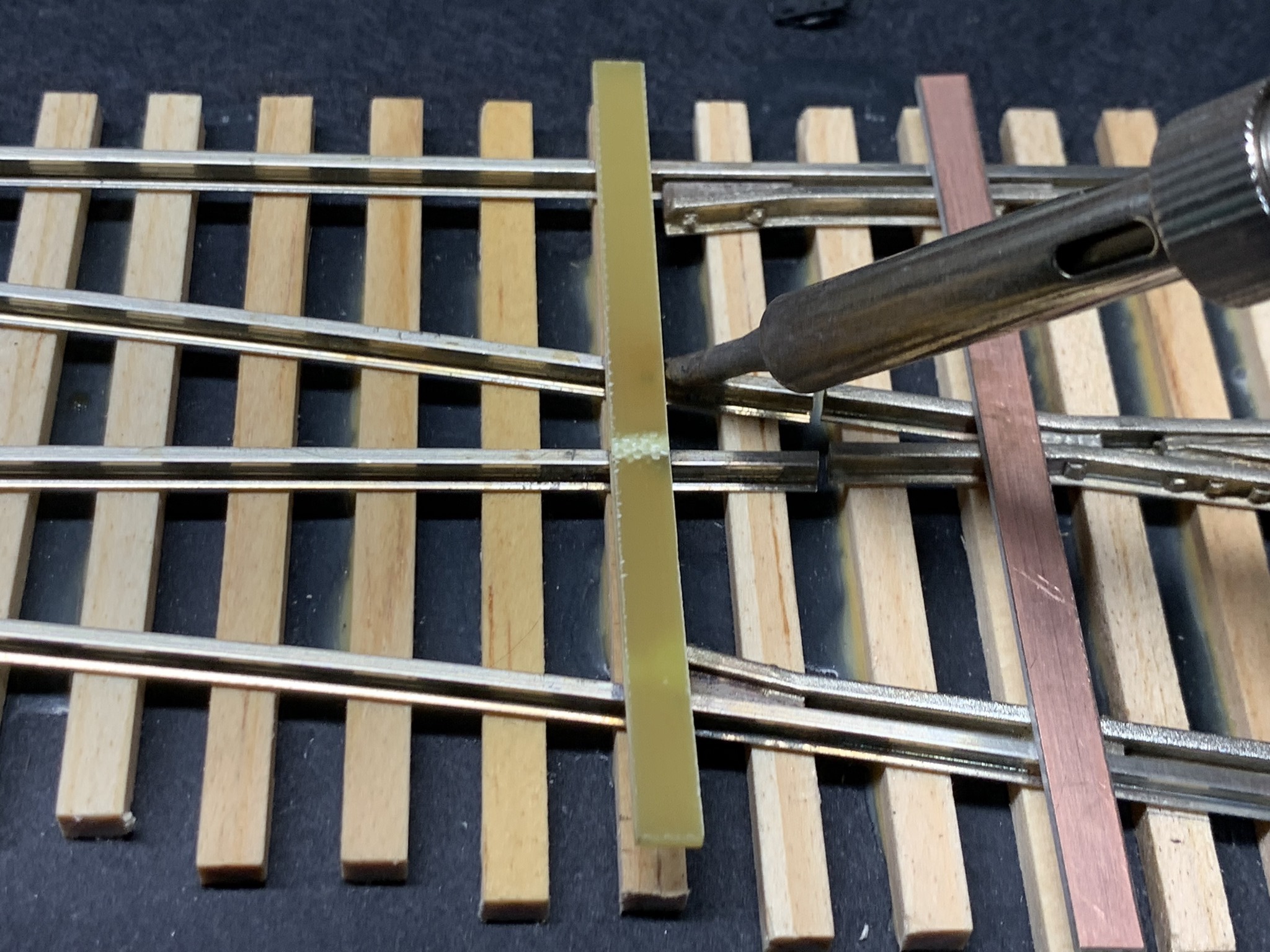
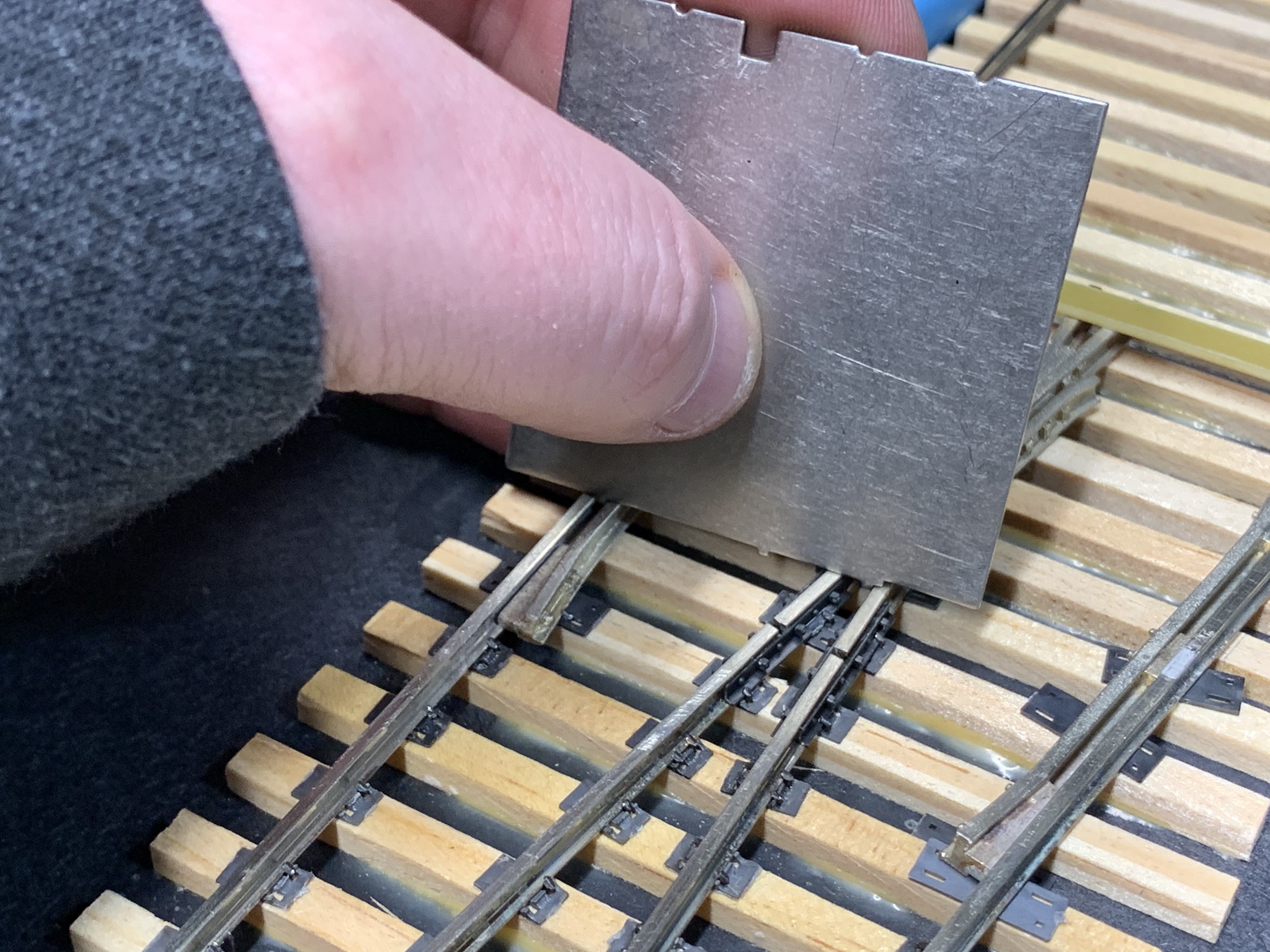
I set the switch in place and marked the rail heads with a felt-tip pen on the tie centers. I then put a label under the switch points and began to solder the rail braces into place. The paper was used to protect the ties from being burnt from the heat from my soldering iron. Now, if you are a fire marshal, please don’t yell too loud. I was very careful and had a squirt bottle of water close by just in case. There may be much better material to use for this, however, the paper worked very well and no burn marks on the paper or wood ties.
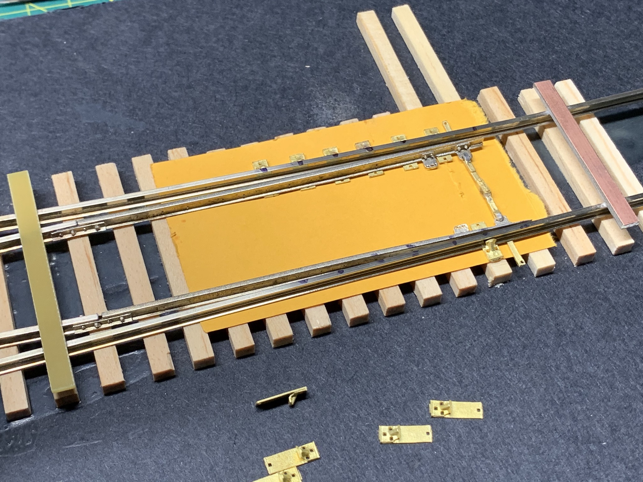
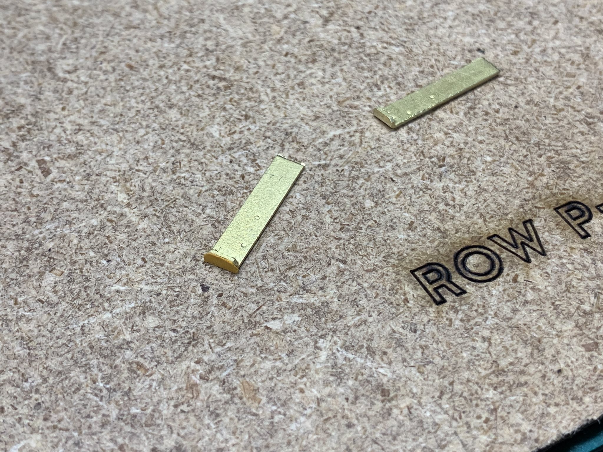
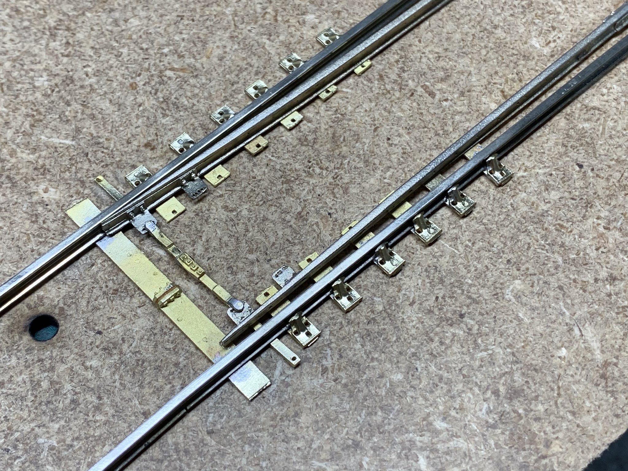
Now for the gauge plate. I create an insulator between the two brass castings by gluing a piece of the label to one end with ACC. When the glue was dry, I trimmed it with an X-Acto knife and glued the two ends together. Although the switch kit come with PC boards soldered to the railheads, you will want to keep a couple of rail gauges handy to ensure that your rails are in gauge when you begin removing the PC boards.
I remove the board at the base of the switch. Then place the rail gauge under the rails and make sure it’s centered. I then solder it in place checking to make sure gauge is correct. To finish the gauge plate, the kit comes with 2 rail braces with out tie plates. I thin the base with a file so they match the height of the other braces and solder them on the ends. Any access flashing was filed down and the gauge plate was trimmed to match the length of the other tie plates. Finally, I use a wire wheel attachment in my motor tool and polish the castings.
At this point, I would consider cleaning everything to remove any oils or residues before you add any of the plastic details. If I were going to paint and weather the switch, I would also do it now before spiking into place. It makes painting much easier!
I spike the switch in place leaving 4 ties between my tie plates and the next PC board. To sweat the PC boards off of the railheads, I used my soldering iron and placed it onto the rail head. The heat will loosen the solder and with tweezers, I can pull it off the rails with very little effort. I then continue spiking the rail down and continue towards the frog and guardrails. I removed the first PC board on the frog then applied the plastic rail joiners to secure the rails to the frog.
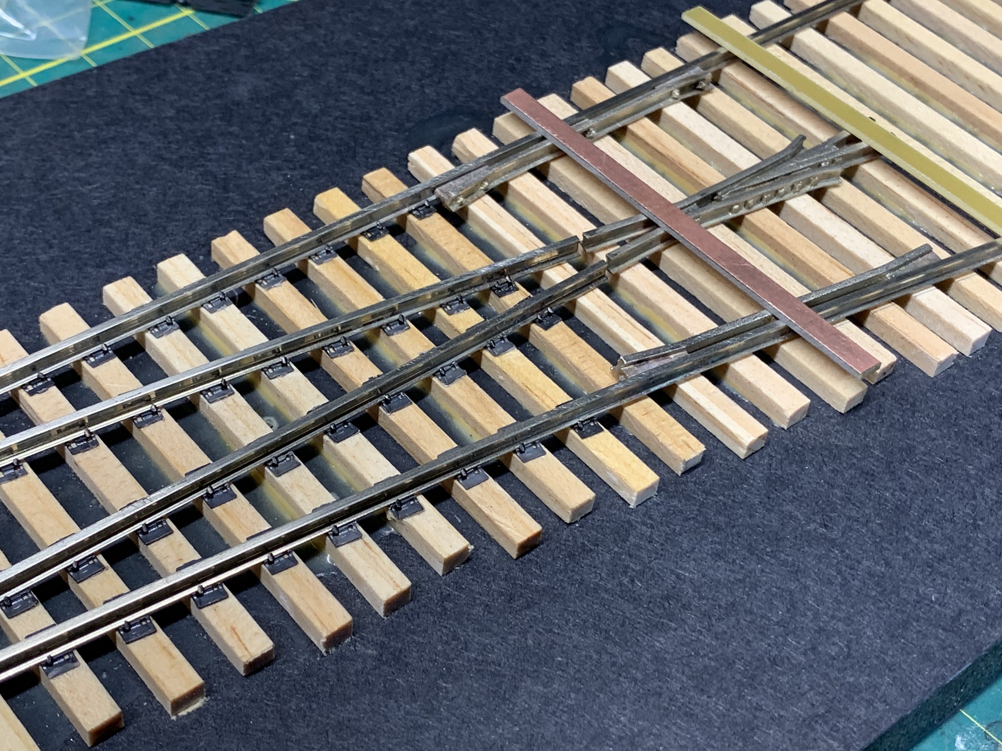
I continue checking gauge as I spike the stock rail first, then the frog. I then check the gauge of the curved stock rail and then spike that into place. Since most of the rail is secured into place, I sweat off the final PC board and continue spiking the frog and stock rails.
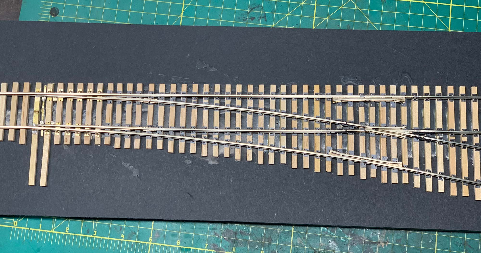
I added the remaining rails along with the plastic rail joiners to complete the kit.
Final Thoughts
I found this kit very easy to build and went together in about four hours after the ties were glued in place and dry. Jay has also mentioned that he plans on offering different size switches as well as rail sizes, depending on response from the modeling community. For those looking to hand lay switches for the first time, this is a great way to get started. For those of you who are well versed at hand-laying track, I see this greatly speeding up production. I have a couple on order and I am looking forward to this kit to make it out of development and available to purchase.

Just what we needed to make certain aspects of the hobby less time consuming and more “productive”. As soon as some of my current workload eases a bit and more (no. 10 and larger) turnouts become available, I also will purchase the kits. Another current Model Manufacturer has also agreed to supply me with certain “O” scale products, if I buy the dollar amount that I suggested, which means that I can finally construct certain segments of my layout. The development of 3D manufacturing for the small production facet of modeling has revolutionized or more properly, “injected new life into our hobby” if only more younger members would expand the “buying and fun base” of this hobby.
[…] few months ago I saw Shawn Branstetter”s Building a Right O’ Way Switch Kit post in his Shortline Modelers Blog and really wanted to try it out. The kits were not on the […]
I just came back from the O Scale National held in Denver last week. The kits were discussed. Are they ready yet?
Dick
I believe Jay has a few 6’s in stock and number 8 in the works. I don’t think the kits are listed on his site. I would reach out to him to confirm
Hello, I am Herbert from Czech republic actually building scale 0 layout after Southern Pacific prototype. I planned to use Atlas turnouts, but after I have seen this very nice handlaid turnout, I would like to use them. Unfortunately, I am not keen in building kits. So my question is, if there is somebody who can build and paint 4 turnouts in the scale 0 from RightOWay or Scale 0 Turnout kits for me. 2x #6, 2x #8, code 125. I pay in advance, I am aware of the building and painting costs and I am not in hurry, delivery at the end of 2022 would be OK. Any advice would be very appreciated. Thank you Herbert
Hi Herbert! I would recommend reaching out to Brad Strong from Signature Switch (http://signatureswitchco.com/). He makes ready to lay and run turnouts in both O scale and Proto48. I’m sure he could build them for you.